05 Run IMU04 in Standalone CAN Operating Modes

Configuring an IMU04 with VBOX Setup
Hardware Connections
- ► IMU04 with 12 V power source
-
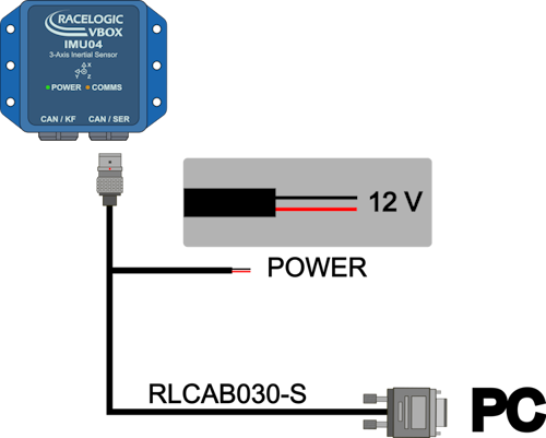
Note: If you do not have a serial port on your PC, you can use a Serial-to-USB converter.
- ► IMU04 powered via VBOX 3i
-
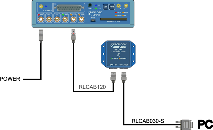
Note: If you do not have a serial port on your PC, you can use a Serial-to-USB converter.
- ► IMU04 powered via VBOX 3i ADAS
-
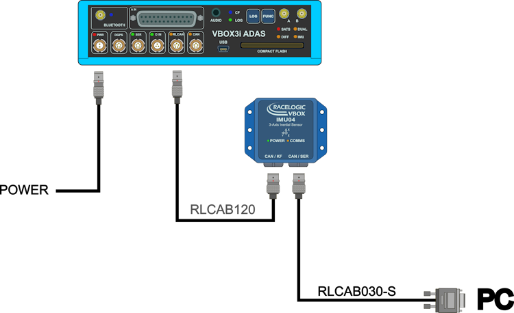
Note: If you do not have a serial port on your PC, you can use a Serial-to-USB converter.
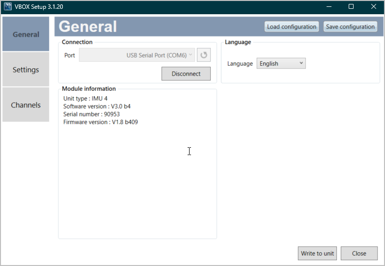
VBOX Setup with IMU04
General Menu
Settings Menu
Racelogic Polled CAN Mode – Default Mode
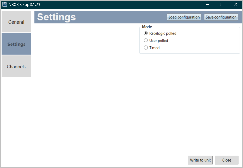
You should use this mode if you are using the unit with a Racelogic VBOX unit. All the CAN parameters are set to work with the Racelogic VBOX CAN protocol. In this mode, you cannot set any parameters yourself.
User Polled CAN Mode
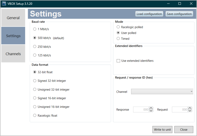
This mode allows a user’s own data logging system to poll the unit for data using the CAN bus. The IMU can be polled up to 100 Hz.
The following parameters are used in this mode:
Baud Rate
The baud rate sets the bit rate of the CAN messages (not the frequency at which the messages are sent).
The IMU has four baud rate options:
- 1 Mbit/s
- 500 kbit/s
- 250 kbit/s
- 125 kbit/s
Data Format
- Channel 1 Yaw_Rate (deg/sec)
- Channel 2 X_Accel (g)
- Channel 3 Y_Accel (g)
- Channel 4 Temp (deg C)
- Channel 5 Pitch_Rate (deg/sec)
- Channel 6 Roll_Rate (deg/sec)
- Channel 7 Z_Accel (g)
Channels are sent as pairs, so channels 1 and 2 will be sent together, 3 and 4 together and so on. The pairing of channels cannot be changed. The channel data is in an IEEE 32-bit float format so each channel occupies 4 bytes. The first 4 data bytes contained within a data packet are the lower channel; the second 4 bytes are for the higher data channel. A CAN DBC file containing default settings for each sensor is available on request from Racelogic.
Extended Identifiers
Tick the respective Xtd boxes for the identifiers you wish to extend from the standard 11-bit format to the extended 29-bit format.
If it is unticked, the CAN identifier type will be standard 11 bit. The standard identifier type allows 2048 different CAN message identifiers or message “names”. The extended identifier type allows 436207616 different CAN message identifiers. The identifier type should be set to match the CAN data logging equipment.
Request / response ID (hex)
The request identifiers will only affect User Polled CAN mode. They set the identifier values that the IMU will filter for. If a CAN message is received that matches a request identifier, the IMU will respond by sending the corresponding channel data on the corresponding response identifier.
Note: All channels can have the same request identifier – this means that on receipt of a single CAN message the IMU will respond with all channels of data. The response identifiers MUST all be different.
In timed mode the channel data will be sent at intervals with the corresponding response identifier – the request identifiers have no effect.
When you are using standard identifiers the maximum value for the identifiers is 0x7FF. Entering a value higher than this may cause unexpected results, for instance a response identifier of 0x00FFAA23 will result in a message being sent with identifier 0x223. To avoid anything unexpected, the request and response identifiers should be set appropriately for use with standard identifiers.
Timed CAN Mode
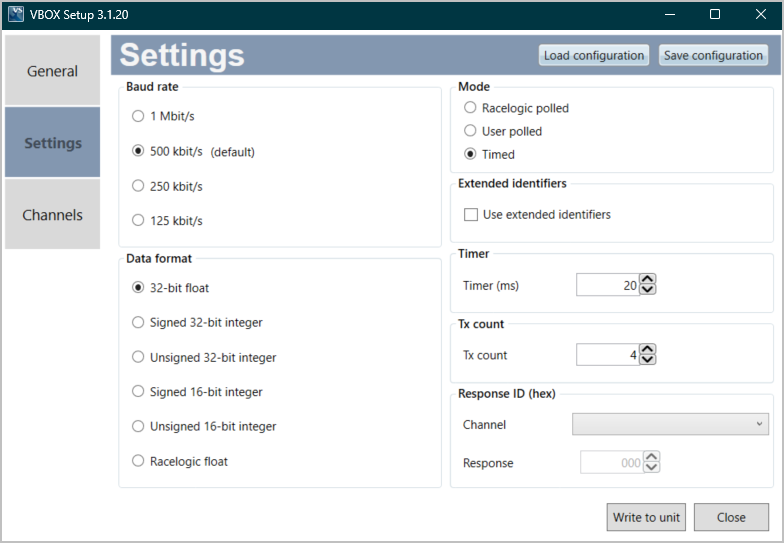
In this mode, the unit will send CAN data at intervals determined by the timer value. The following parameters are used in this mode:
Baud Rate
The baud rate sets the bit rate of the CAN messages (not the frequency at which the messages are sent).
The IMU has four baud rate options:
- 1 Mbit/s
- 500 kbit/s
(The default setting is 500 Kbit/s as most light vehicles use that baud rate. If you want to change the baud rate, you can find the setting in the CAN menu in the VBOX Setup software.) - 250 kbit/s
- 125 kbit/s
Data Format
- Channel 1 Yaw_Rate (deg/sec)
- Channel 2 X_Accel (g)
- Channel 3 Y_Accel (g)
- Channel 4 Temp (deg C)
- Channel 5 Pitch_Rate (deg/sec)
- Channel 6 Roll_Rate (deg/sec)
- Channel 7 Z_Accel (g)
Channels are sent as pairs, so channels 1 and 2 will be sent together, 3 and 4 together and so on. The pairing of channels cannot be changed. The channel data is in an IEEE 32-bit float format so each channel occupies 4 bytes. The first 4 data bytes contained within a data packet are the lower channel; the second 4 bytes are for the higher data channel. A CAN DBC file containing default settings for each sensor is available on request from Racelogic.
Extended Identifiers
Tick the respective Xtd boxes for the identifiers you wish to extend from the standard 11-bit format to the extended 29-bit format.
If it is unticked, the CAN identifier type will be standard 11 bit. The standard identifier type allows 2048 different CAN message identifiers or message “names”. The extended identifier type allows 436207616 different CAN message identifiers. The identifier type should be set to match the CAN data logging equipment.
Timer
When selecting Timed Mode, the option to set the Timer value will appear.
The timer value is in milliseconds (ms). A smaller value means that the data will be sent more frequently and a larger value means that the data will be sent less frequently. The value range is 0 to 65535, but the minimum value that should be entered is 10. If you set it below 10, the data values may be repeated on successive cycles. If you enter a value of 0 , the IMU unit will change it to 1000 on the next power cycle.
How to calculate the frequency output:
Freq = (1/Timer) * 1000
How to calculate the timer value for a required frequency:
Timer = (1/Freq) * 1000
The following table shows some example timer values against the frequency output.
| Timer Value (ms) | Frequency (Hz) |
|---|---|
| 10 | 100 |
| 50 | 20 |
| 100 | 10 |
| 400 | 2.5 |
| 1000 | 1 |
Note: When any change is made with the VBOX Setup Software, you must power-cycle the unit for the changes to take effect.
Tx Count
The TX count is the number of CAN channels transmitted, between 1 and 4.
Channels Menu
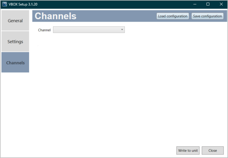
Use the dropdown menu to see the available channels and select the one you wish to use.
- YawRate
- X_Accel
- Y_Accel
- Temp
- PitchRate
- RollRate
- Z_Accel

When you have selected the channel you wish to configure from the dropdown menu, you can adjust the scale and offset for it.