02 Installing VBOX 3iS Dual Antenna RTK in your vehicle
Mounting
When installing the VBOX 3iS Dual Antenna RTK in your vehicle, you can either fix it rigidly to the vehicle using the fixing holes or secure it with a telescopic mounting arm.
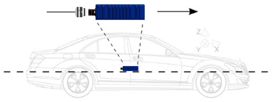
Try to position the unit as close to the centre of the vehicle as possible, and make sure that it is level with the ground. If you are using the internal IMU, you should ideally mount the unit in the direction of travel (as shown in the image below). If this is not possible, you can change the orientation of the internal IMU in the VBOX Setup Software, on the Front Panel, or with the VBOX Manager.
Note: VBOX 3iS and the antenna should be mounted on the same rigid body to provide a relative reference. So for a vehicle such as a truck cabin, both the VBOX 3iS and the antenna should be fitted to the cabin body (if the cabin is air-sprung) or to the vehicle chassis.
Fixed Mounting
You can mount VBOX 3iS rigidly to the vehicle via the fixing holes, ideally mid-way along the wheelbase.
Using a Mounting Arm
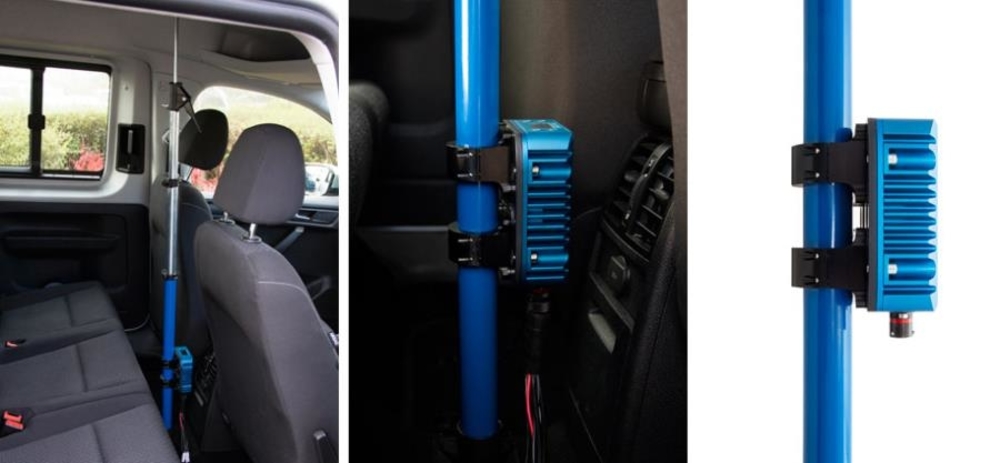
A flexible way to fix the VBOX 3iS rigidly in the vehicle is by using the Racelogic Mounting Arm. The three-part telescopic handle is fully adjustable to any length between 70 – 150 cm, another 20 cm can be added by extending the third section using the compression lever.
Both ends are fixed to an 8 x 13 cm plate which sits on a joint to accommodate uneven surfaces. The VBOX 3iS can then be pressed against the floor and the vehicle's ceiling, ensuring that the VBOX 3iS is fixed tightly. Another option is to use a bracket that attaches to the mounting arm, meaning that the VBOX 3iS can be fixed to the mounting arm before being installed within the vehicle. If using the bracket, it is recommended that the VBOX 3iS is mounted vertically towards the bottom of the pole for greater stability.
Please contact vbox@racelogic.co.uk for more information or to order a mounting arm (RLACS212-V2) and/or mounting bracket (RLACS291).
Antenna Placement
Appropriate placement of the GNSS antenna is crucial to the quality of the data that is being recorded.
Be aware of objects that can shadow the antenna or block the signal to the antenna. Some objects can also reflect signals which can send weaker GNSS signals to the antenna. This is called multipath, and these reflections can disturb the signal in an unpredictable way.
If an antenna is not mounted on a large enough ground plane, multipath reflections can also come from the ground beneath the antenna.
You can find more information about how to mount antennas here.
Hardware Connections
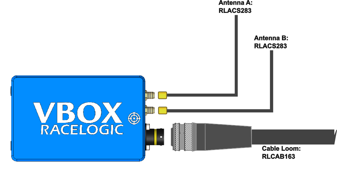
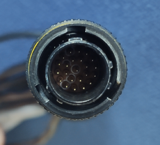
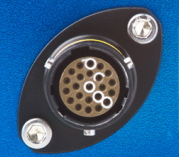
Connecting the Loom to the VBOX Unit
| Note: It is important that you do not use force when connecting and disconnecting the loom to the VBOX unit. |
 |
 |
|
|
|
 |
 |
 |
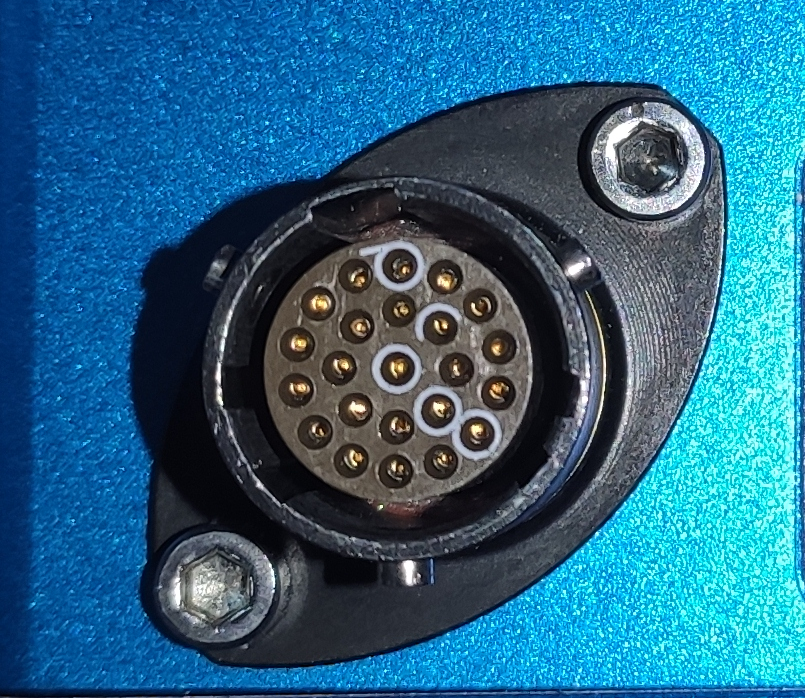
| Push the connectors gently together and twist the outer ring on the loom's connector until it slots in place and locks the connection. | ||
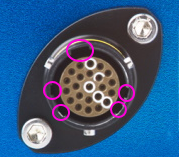
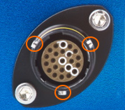
Disconnecting the Loom From the VBOX Unit
Note the notches on the connectors as illustrated above. Twist the loom's connector while you gently pull it away from the unit.