Inputs/Outputs – VBOX 3i ADAS
Interfaces
100 Hz GNSS Engine
VBOX 3i ADAS features a powerful multi-frequency, multi-constellation GNSS engine with improved RTK performance.
Dual Antenna
By utilising two GNSS antennas, you get accurate, non-drift measurements of the vehicle body's heading.
VBOX 3i ADAS uses dual antennas to project vehicle offset points and to produce accurate, low-noise ADAS measurements.
Compact Flash
VBOX 3i ADAS uses Type I compact flash cards to log data. Data is stored in a standard PC format, that allows for fast transfer of data to a PC equipped with a compact flash card reader.
VBOX 3i ADAS RS232 / CAN Ports
You can find more information about the VBOX 3i RS232 protocol here.
| DGPS | This port is for connection to a DGPS Radio or NTRIP Modem. This allows the VBOX unit to receive Differential GPS (DGPS) data from a Racelogic Local DGPS base station or Moving Base solution to provide local correction. |
| SER |
This port is for use with ADAS radios. |
| RLCAN | The RLCAN port is termination enabled for connection to Racelogic modules and devices. |
| CAN | For connection to third-party CAN bus. |
Analogue Inputs
You can see the PIN outs of the Analogue Input Connector here.
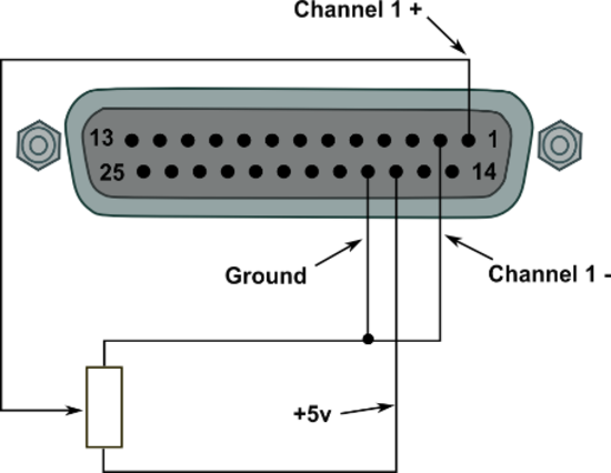
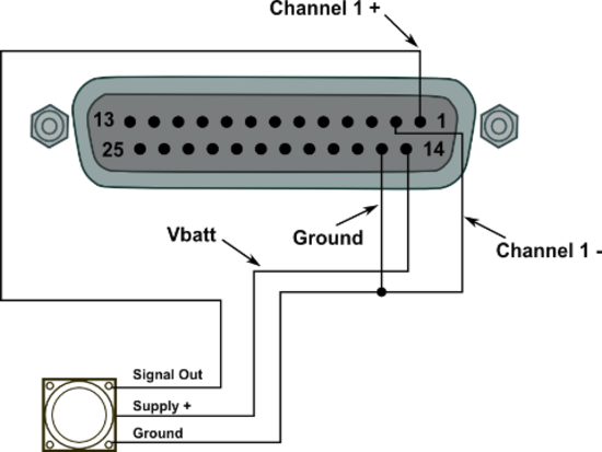
The VBOX 3i ADAS contains four differential 24-bit analogue input channels with a maximum sample rate of 500 Hz. Each channel has its own dedicated analogue to digital (A/D) converter with all four channels being sampled synchronously to each other. The voltage range of the input channels is ±50 V. Note that, unlike the ADC03 module, the analogue channels in the VBOX 3i ADAS are not electrically isolated from each other.
The analogue input connector also contains voltage outputs that can be used to power external sensors. These are a Vbatt connection which is equal to the VBOX units input voltage level and a 5 V DC out connection which is equal to 5 V ±2%.
- VBOX 3i ADAS: The 5 V out connection is electrically isolated, allowing for up to 120 mA of current to be drawn.
The Vbatt connection is internally protected by a thermal fuse.
- VBOX 3i ADAS: 300 mA
A screw-terminal connector block is available as an option for easy connection of signal pins.
 |
 |
Note: A 25 W D-sub to 4 W BNC adaptor block is available through your VBOX distributor, part number RLVBACS054
By using VBOX Setup software you can change the name of each input channel and configure scale and offset values for calibration of sensors. A scale value of 1 and an offset of 0 correspond to a channeled reading in V DC. This means that the value stored on the compact flash card for the channel will also be in volts. When using a sensor such as a load cell, it may be desirable to store reading in kg. In this case, changing the scale and offset to suit the sensor data sheet allows the data stored onto the compact flash to be in kg. When changing settings for an analogue channel in the VBOX Setup software, you can see a live data view of the current channel. The value shown is the value after scale and offset are applied and can, therefore, be used to aid sensor calibration.
Note: The 5 V regulated output on pin 16 is only good for VBOX power supply voltages > 8.5 V
 |
| AD channel properties in the Channel Config menu in VBOX Setup |
500 Hz logging
VBOX 3i ADAS units have the ability to log 4 analogue channels at 500 Hz. With this feature enabled, the file sizes will increase. You can enable 500 Hz logging for internal analogue and digital inputs in VBOX Setup, in the Logging menu.
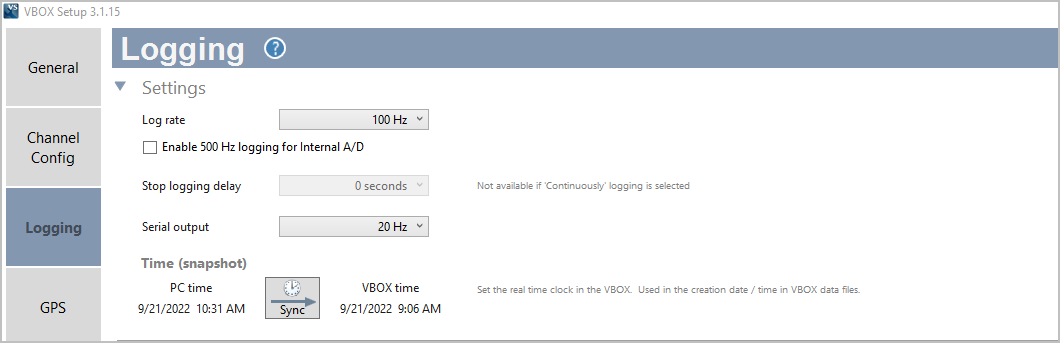 |
| VBOX Setup A/D 500 Hz |
Digital InputsThe ‘D IN’ connector contains the two digital inputs for the VBOX 3i ADAS.
|
 |
| You can connect two digital input devices to the VBOX 3i with the use of an additional splitter box, as shown in the image below. |
 |