4.1 IMU Integration
Click on the IMU version you are using to see the relevant IMU integration instructions.
- ►IMU04
-
Required Equipment
- VBOX 3i unit (with firmware version 3.0 or later)
- GNSS antenna(s)
- Power Cable/Battery pack
- IMU04 unit
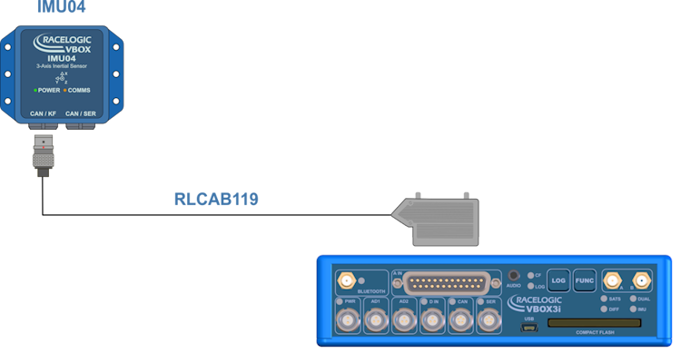
- RLCAB119 – VBOX - IMU connecting cable
- RLCAB001 / RLCAB066-2 - VBOX 3i PC connection cable
- VBOX Setup
- VBOX Manager (optional)
- RLCAB069L / RLCAB015L / RLACS182L - vehicle CAN bus cable (optional for wheel speeds)
Hardware Setup
IMPORTANT
IMU04 must be connected to VBOX 3i before power is applied to ensure data is correctly synchronised.
- Place the VBOX 3i unit in the test vehicle, and mount the IMU as described here.
- Connect the VBOX 3i GNSS antenna(s) to the centre of the vehicle roof. Connect the antenna(s) to the VBOX unit.
- If your IMU is mounted inside the vehicle, you must measure the relative position from the top centre of the GNSS antenna* to the top centre of the IMU (see the mounting section for more detail). Measurements need to be made in all 3 axes, X, Y and Z.
*When using a twin antenna system, these measurements must be taken from the primary antenna (A). - Use the Lemo connector on the RLCAB119 cable to the CAN/KF port on the IMU unit.
- Connect the analog input connector on the RLCAB119 to the analogue input port on the VBOX 3i unit.
- Apply power to the VBOX 3i unit.
VBOX 3i Single Antenna
_750px.png?revision=1)
VBOX 3i Single Antenna V3-V5 with IMU04 VBOX 3i Dual Antenna
VBOX 3i Dual Antenna V3-V5 with IMU04 VBOX 3i RTK
VBOX 3i RTK V3-V5 with IMU04 Configuration
VBOX Setup Software
- Make sure that the IMU04 is connected to the VBOX 3i unit and that the VBOX 3i is powered on.
- Connect the VBOX 3i unit to your PC with the RLCAB001 cable (RS232) or the RLCAB066-2 cable (USB).
- Open VBOX Setup and connect to the VBOX 3i unit by selecting the relevant COM Port.
- Open the Logging menu and make sure that the Log rate is set to 100 Hz.
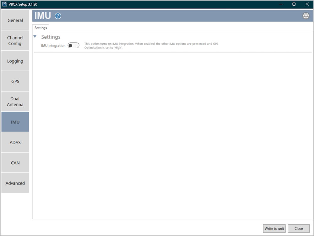
- Open the IMU menu and enable the IMU integration.

- Configure the IMU based on where it is mounted:
- If you have mounted your IMU on the roof, you must enable the Roof mount option.

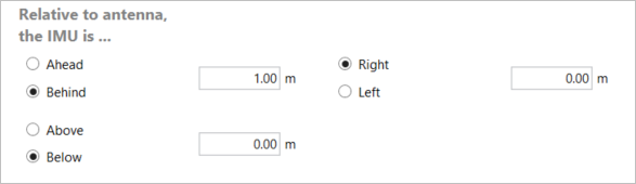
- If you have mounted your IMU in the vehicle, you must enter the distance measurements between the IMU and the primary antenna (A). You can find more information on this here.
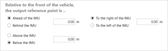
- Enter measurements for the output reference point relative to the front of the vehicle.
- The IMU Attitude channels (Head_imu, Pitch_imu, Roll_imu, Pos.Qual., Lng_Jerk, Lat_Jerk and Head_imu2) will be set to log automatically.
- The Serial IMU channels (x accel, y accel, z accel, temp, pitch rate, roll rate and yaw rate) will also be set to log automatically.
Notes:
If you want to view the CAN data live, you must have a multi-functional display (e.g. MFD Touch) connected and tick the Send to MFD box for the channel. If you want to display the IMU Attitude data as a Live Serial data display and you are using an alternative software to VBOX Test Suite, you must tick the Advanced box in the top right corner and tick the Send over serial box for the relevant channels.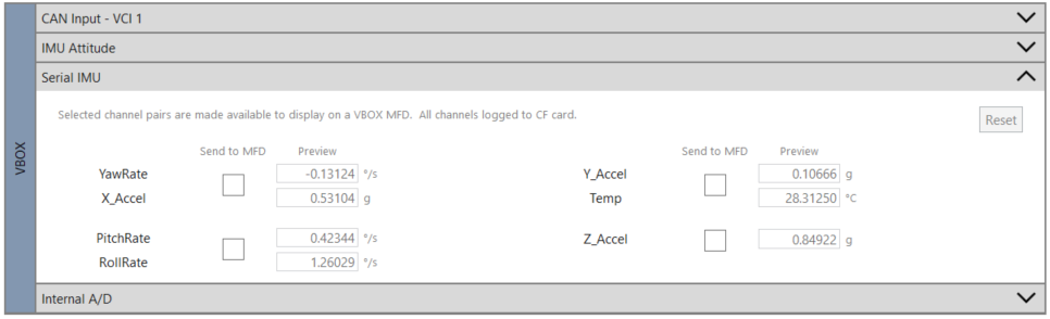
- Click on the Write to unit button to upload the new configurations to the VBOX 3i unit.
- Perform the Kalman Filter Calibration.
- Perform the IMU Calibration process in the IMU menu in VBOX Setup.
Wheel Speed Inputs
Vehicle speed data can be combined with inertial IMU data to provide increased data accuracy in environments that have poor satellite reception, such as areas with trees, buildings, bridges or tunnels. You can find more information on this here.
To obtain the wheel speed information, the best method is to use the sensors that are already fitted to the vehicle by connecting to the vehicle’s CAN bus with an RLCAB069L, RLCAB015L or RLACS182L cable. Before you start testing, you must make sure that the VBOX 3i unit is correctly connected to either the speed sensors or to the vehicle CAN bus.
Next, you need to enable and configure the wheel speed input in the VBOX Setup software.
- Make sure that the IMU04 is connected via RLCAB119, and that the VBOX 3i is powered on.
- Connect your VBOX 3i to a computer, either via Bluetooth (an RLCAB001 cable to the SER input and the computer's serial port, you may need a usb-serial adapter), or via an RLCAB066-2 cable to one of the computer's USB ports.
- Open VBOX Setup and connect to VBOX 3i by selecting the relevant COM Port.
- Open the IMU menu and select the Wheel speed input tab.
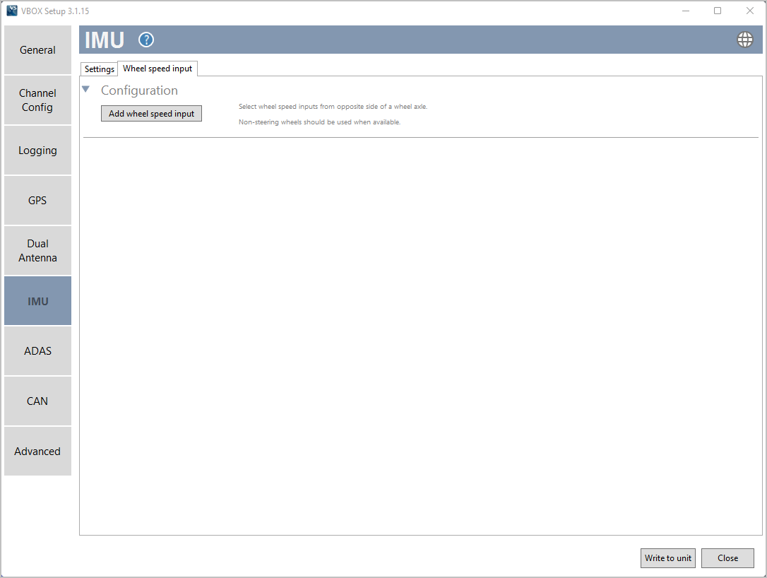
- Click the Add wheel speed input to start configuring the inputs.
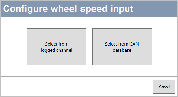
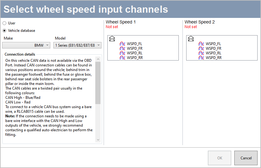
Configuration option sources From CAN database - Configure the inputs by selecting the applicable input for each wheel speed.
- Click OK
- Select Write to unit to save the settings.
VBOX Manager
- Make sure that the IMU04 is connected to the VBOX 3i unit and that the VBOX 3i unit is powered on.
- Connect VBOX Manager to the VBOX 3i unit.
- Enter the SETUP menu of VBOX Manager.
- Select IMU-INS and then click on the IMU Integration menu.


- Scroll to Enable and select. Once the OK confirmation screen has cleared, Enabled will be displayed.


- Scroll to the Roof Mount menu and enable it if relevant.

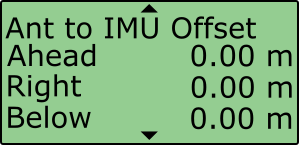
- If you do not enable Roof Mount, navigate to the Ant to IMU Offset setting and enter the distances measured between the IMU and the primary antenna (A). You can find more information about the Antenna offsets here.
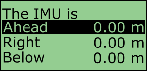
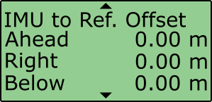
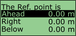
- If you would like to translate the data from the IMU location to another point on the vehicle where all measurements will be made, Select 'IMU to Ref. Offset' and enter the distances measured between the required translation point and the IMU, more information on this can be found here.
- Internal IMU Attitude channels (Head_imu, Pitch_imu, Roll_imu, Pos.Qual., Lng_Jerk, Lat_Jerk and Head_imu2) will automatically be set to log. If IMU Attitude data is required to be displayed as a Live Serial data display (with VBOX Test Suite), then the user must enter VBOX Setup Software and tick the channels for Send over serial.
- Perform initialisation and full calibration procedure before commencing testing.
- If the IMU is not mounted on a flat surface, perform Pitch/Roll Offset calibration.
This will zero the Pitch_imu and Roll_imu channels. Angle offsets calibration must be performed after the IMU kalman filter calibration has been completed, and the vehicle is static on a level surface.

- If you are conducting ADAS testing, you must make sure that the ADAS Mode menu shows Enabled.
This setting changes the rate at which the Kalman filter takes a GPS positional sample to improve the positional performance of the filter. Whilst this is beneficial to ADAS testing, it slightly decreases the accuracy of the filtered speed and therefore shouldn't be selected when undertaking speed-based testing such as brake stops.
 E
EIMPORTANT
- To use IMU04 integration, you must use a VBOX 3i V3, V4 or V5 with firmware version 3.0 or later. These are IMU04-enabled VBOX 3i units.
- IMU04 cannot be used with IMU integration if it is connected to a VBOX via CAN (RLCAB120 / RLCAB005-CS). This method of connection will only allow standard IMU channels to be logged. See the using IMU as CAN module section for details.
- The IMU04 standard channels can also be logged when the IMU04 is connected via KF port with cable RLCAB119, without enabling IMU integration.
- The IMU04 must be in a Racelogic CAN mode to be used for IMU Kalman Filter.
- ADAS Applications - If using IMU Integration with an ADAS mode, the GNSS antenna and IMU should be co-located (roof mount) or positioned so there is no relative X or Y offset between them. If there is a difference, manual contact points should reference the IMU location, rather than the GNSS antenna.
- ADAS Applications - When using IMU Integration, the user cannot use the Set Points functionality to define contact points in single or multi-target ADAS modes.
Initialisation
When using IMU integration, an initialisation phase is required when the IMU is first connected to the VBOX after being set up. This will be run through automatically after the VBOX has successfully gained satellite lock. When the IMU LED on VBOX 3i front panel has turned a flashing green, the initialisation is complete.
LED Indicators IMU04
IMU04 LED Colour Power Coms Red Initial boot up phase. No coms. Orange Temperature checks. If temperature outside optimum operation range, LED will remain orange. Using IMU integration, inertial data being sent to host VBOX via RS232. Green Fully operational. Inertial data being sent to host system via CAN.
- ►IMU05
-
Required Equipment
- VBOX 3i unit (with firmware version 3.0 or later)
- GNSS antenna(s)
- Power Cable/Battery pack
- IMU05 unit
- RLCAB119 – VBOX - IMU connecting cable
- RLCAB001 / RLCAB066-2 - VBOX 3i PC connection cable
- VBOX Setup
- VBOX Manager (optional)
- RLCAB069L / RLCAB015L / RLACS182L - vehicle CAN bus cable (optional for wheel speeds)
Hardware Setup
IMPORTANT
IMU05 must be connected to VBOX 3i before power is applied to ensure data is correctly synchronised.
- Place the VBOX 3i unit in the test vehicle, and mount the IMU as described here.
- Connect the VBOX 3i GNSS antenna(s) to the centre of the vehicle roof. Connect the antenna(s) to the VBOX unit.
- If your IMU is mounted inside the vehicle, you must measure the relative position from the top centre of the GNSS antenna* to the top centre of the IMU (see the mounting section for more detail). Measurements need to be made in all 3 axes, X, Y and Z.
*When using a twin antenna system, these measurements must be taken from the primary antenna (A). - Use the Lemo connector on the RLCAB119 cable to the CAN/KF port on the IMU unit.
- Connect the analog input connector on the RLCAB119 to the analogue input port on the VBOX 3i unit.
- Apply power to the VBOX 3i unit.
VBOX 3i Single Antenna
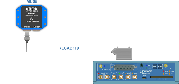
VBOX 3i Single Antenna V3-V5 with IMU05 VBOX 3i Dual Antenna
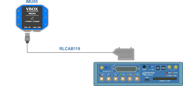
VBOX 3i Dual Antenna V3-V5 with IMU05 VBOX 3i RTK
VBOX 3i RTK V3-V5 with IMU05 Configuration
VBOX Setup Software
- Make sure that the IMU05 is connected to the VBOX 3i unit and that the VBOX 3i is powered on.
- Connect the VBOX 3i unit to your PC with the RLCAB001 cable (RS232) or the RLCAB066-2 cable (USB).
- Open VBOX Setup and connect to the VBOX 3i unit by selecting the relevant COM Port.
- Open the Logging menu and make sure that the Log rate is set to 100 Hz.
- Open the IMU menu and enable the IMU integration.
- Configure the IMU based on where it is mounted:
- If you have mounted your IMU on the roof, you must enable the Roof mount option.
- If you have mounted your IMU in the vehicle, you must enter the distance measurements between the IMU and the primary antenna (A). You can find more information on this here.
- Enter measurements for the output reference point relative to the front of the vehicle.
- The IMU Attitude channels (Head_imu, Pitch_imu, Roll_imu, Pos.Qual., Lng_Jerk, Lat_Jerk and Head_imu2) will be set to log automatically.
- The Serial IMU channels (x accel, y accel, z accel, temp, pitch rate, roll rate and yaw rate) will also be set to log automatically.
Notes:
If you want to view the CAN data live, you must have a multi-functional display (e.g. MFD Touch) connected and tick the Send to MFD box for the channel. If you want to display the IMU Attitude data as a Live Serial data display and you are using an alternative software to VBOX Test Suite, you must tick the Advanced box in the top right corner and tick the Send over serial box for the relevant channels. - Click on the Write to unit button to upload the new configurations to the VBOX 3i unit.
- Perform the Kalman Filter Calibration.
- Perform the IMU Calibration process in the IMU menu in VBOX Setup.
Wheel Speed Inputs
Vehicle speed data can be combined with inertial IMU data to provide increased data accuracy in environments that have poor satellite reception, such as areas with trees, buildings, bridges or tunnels. You can find more information on this here.
To obtain the wheel speed information, the best method is to use the sensors that are already fitted to the vehicle by connecting to the vehicle’s CAN bus with an RLCAB069L, RLCAB015L or RLACS182L cable. Before you start testing, you must make sure that the VBOX 3i unit is correctly connected to either the speed sensors or to the vehicle CAN bus.
Next, you need to enable and configure the wheel speed input in the VBOX Setup software.
- Make sure that the IMU05 is connected via RLCAB119, and that the VBOX 3i is powered on.
- Connect your VBOX 3i to a computer, either via Bluetooth (an RLCAB001 cable to the SER input and the computer's serial port, you may need a usb-serial adapter), or via an RLCAB066-2 cable to one of the computer's USB ports.
- Open VBOX Setup and connect to VBOX 3i by selecting the relevant COM Port.
- Open the IMU menu and select the Wheel speed input tab.
- Click the Add wheel speed input to start configuring the inputs.
Configuration option sources From CAN database - Configure the inputs by selecting the applicable input for each wheel speed.
- Click OK
- Select Write to unit to save the settings.
VBOX Manager
- Make sure that the IMU05 is connected to the VBOX 3i unit and that the VBOX 3i unit is powered on.
- Connect VBOX Manager to the VBOX 3i unit.
- Enter the SETUP menu of VBOX Manager.
- Select IMU-INS and then click on the IMU Integration menu.
- Scroll to Enable and select. Once the OK confirmation screen has cleared, Enabled will be displayed.
- Scroll to the Roof Mount menu and enable it if relevant.
- If you do not enable Roof Mount, navigate to the Ant to IMU Offset setting and enter the distances measured between the IMU and the primary antenna (A). You can find more information about the Antenna offsets here.
- If you would like to translate the data from the IMU location to another point on the vehicle where all measurements will be made, Select 'IMU to Ref. Offset' and enter the distances measured between the required translation point and the IMU, more information on this can be found here.
- Internal IMU Attitude channels (Head_imu, Pitch_imu, Roll_imu, Pos.Qual., Lng_Jerk, Lat_Jerk and Head_imu2) will automatically be set to log. If IMU Attitude data is required to be displayed as a Live Serial data display (with VBOX Test Suite), then the user must enter VBOX Setup Software and tick the channels for Send over serial.
- Perform initialisation and full calibration procedure before commencing testing.
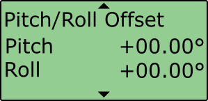
- If the IMU is not mounted on a flat surface, perform Pitch/Roll Offset calibration.
This will zero the Pitch_imu and Roll_imu channels. Angle offsets calibration must be performed after the IMU kalman filter calibration has been completed, and the vehicle is static on a level surface.
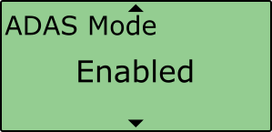
- If you are conducting ADAS testing, you must make sure that the ADAS Mode menu shows Enabled.
This setting changes the rate at which the Kalman filter takes a GPS positional sample to improve the positional performance of the filter. Whilst this is beneficial to ADAS testing, it slightly decreases the accuracy of the filtered speed and therefore shouldn't be selected when undertaking speed-based testing such as brake stops.
EIMPORTANT
- To use IMU05 integration, you must use a VBOX 3i V3, V4 or V5 with firmware version 3.0 or later. These are IMU05-enabled VBOX 3i units.
- IMU05 cannot be used with IMU integration if it is connected to a VBOX via CAN (RLCAB120 / RLCAB005-CS). This method of connection will only allow standard IMU channels to be logged. See the using IMU as CAN module section for details.
- The IMU05 standard channels can also be logged when the IMU05 is connected via KF port with cable RLCAB119, without enabling IMU integration.
- The IMU05 must be in a Racelogic CAN mode to be used for IMU Kalman Filter.
- ADAS Applications - If using IMU Integration with an ADAS mode, the GNSS antenna and IMU should be co-located (roof mount) or positioned so there is no relative X or Y offset between them. If there is a difference, manual contact points should reference the IMU location, rather than the GNSS antenna.
- ADAS Applications - When using IMU Integration, the user cannot use the Set Points functionality to define contact points in single or multi-target ADAS modes.
Initialisation
When using IMU integration, an initialisation phase is required when the IMU is first connected to the VBOX after being set up. This will be run through automatically after the VBOX has successfully gained satellite lock. When the IMU LED on VBOX 3i front panel has turned a flashing green, the initialisation is complete.
LED Indicators IMU05
IMU05 LED Colour Power Coms Red Initial boot up phase. No coms. Orange Temperature checks. If temperature outside optimum operation range, LED will remain orange. Using IMU integration, inertial data being sent to host VBOX via RS232. Green Fully operational. Inertial data being sent to host system via CAN.
- ►IMU05-S
-
Required Equipment
- VBOX 3i unit (with firmware version 3.0 or later)
- GNSS antenna(s)
- Power Cable/Battery pack
- IMU05-S unit
- RLCAB119 – VBOX - IMU connecting cable
- RLCAB001 / RLCAB066-2 - VBOX 3i PC connection cable
- VBOX Setup
- VBOX Manager (optional)
- RLCAB069L / RLCAB015L / RLACS182L - vehicle CAN bus cable (optional for wheel speeds)
Hardware Setup
IMPORTANT
IMU05-S must be connected to VBOX 3i before power is applied to ensure data is correctly synchronised.
- Place the VBOX 3i unit in the test vehicle, and mount the IMU as described here.
- Connect the VBOX 3i GNSS antenna(s) to the centre of the vehicle roof. Connect the antenna(s) to the VBOX unit.
- If your IMU is mounted inside the vehicle, you must measure the relative position from the top centre of the GNSS antenna* to the top centre of the IMU (see the mounting section for more detail). Measurements need to be made in all 3 axes, X, Y and Z.
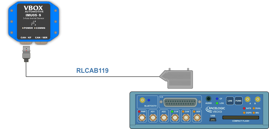
*When using a twin antenna system, these measurements must be taken from the primary antenna (A). - Use the Lemo connector on the RLCAB119 cable to the CAN/KF port on the IMU unit.
- Connect the analog input connector on the RLCAB119 to the analogue input port on the VBOX 3i unit.
- Apply power to the VBOX 3i unit.
VBOX 3i Single Antenna
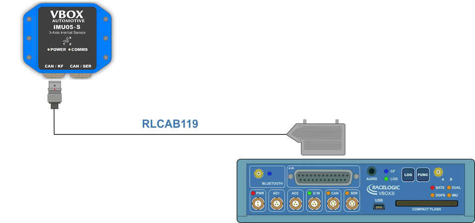
VBOX 3i Single Antenna V3-V5 with IMU05-S VBOX 3i Dual Antenna
VBOX 3i Dual Antenna V3-V5 with IMU05-S VBOX 3i RTK
VBOX 3i RTK V3-V5 with IMU05-S Configuration
VBOX Setup Software
- Make sure that the IMU05-S is connected to the VBOX 3i unit and that the VBOX 3i is powered on.
- Connect the VBOX 3i unit to your PC with the RLCAB001 cable (RS232) or the RLCAB066-2 cable (USB).
- Open VBOX Setup and connect to the VBOX 3i unit by selecting the relevant COM Port.
- Open the Logging menu and make sure that the Log rate is set to 100 Hz.
- Open the IMU menu and enable the IMU integration.
- Configure the IMU based on where it is mounted:
- If you have mounted your IMU on the roof, you must enable the Roof mount option.
- If you have mounted your IMU in the vehicle, you must enter the distance measurements between the IMU and the primary antenna (A). You can find more information on this here.
- Enter measurements for the output reference point relative to the front of the vehicle.
- The IMU Attitude channels (Head_imu, Pitch_imu, Roll_imu, Pos.Qual., Lng_Jerk, Lat_Jerk and Head_imu2) will be set to log automatically.
- The Serial IMU channels (x accel, y accel, z accel, temp, pitch rate, roll rate and yaw rate) will also be set to log automatically.
Notes:
If you want to view the CAN data live, you must have a multi-functional display (e.g. MFD Touch) connected and tick the Send to MFD box for the channel. If you want to display the IMU Attitude data as a Live Serial data display and you are using an alternative software to VBOX Test Suite, you must tick the Advanced box in the top right corner and tick the Send over serial box for the relevant channels. - Click on the Write to unit button to upload the new configurations to the VBOX 3i unit.
- Perform the Kalman Filter Calibration.
- Perform the IMU Calibration process in the IMU menu in VBOX Setup.
Wheel Speed Inputs
Vehicle speed data can be combined with inertial IMU data to provide increased data accuracy in environments that have poor satellite reception, such as areas with trees, buildings, bridges or tunnels. You can find more information on this here.
To obtain the wheel speed information, the best method is to use the sensors that are already fitted to the vehicle by connecting to the vehicle’s CAN bus with an RLCAB069L, RLCAB015L or RLACS182L cable. Before you start testing, you must make sure that the VBOX 3i unit is correctly connected to either the speed sensors or to the vehicle CAN bus.
Next, you need to enable and configure the wheel speed input in the VBOX Setup software.
- Make sure that the IMU05-S is connected via RLCAB119, and that the VBOX 3i is powered on.
- Connect your VBOX 3i to a computer, either via Bluetooth (an RLCAB001 cable to the SER input and the computer's serial port, you may need a usb-serial adapter), or via an RLCAB066-2 cable to one of the computer's USB ports.
- Open VBOX Setup and connect to VBOX 3i by selecting the relevant COM Port.
- Open the IMU menu and select the Wheel speed input tab.
- Click the Add wheel speed input to start configuring the inputs.
Configuration option sources From CAN database - Configure the inputs by selecting the applicable input for each wheel speed.
- Click OK
- Select Write to unit to save the settings.
VBOX Manager
- Make sure that the IMU05-S is connected to the VBOX 3i unit and that the VBOX 3i unit is powered on.
- Connect VBOX Manager to the VBOX 3i unit.
- Enter the SETUP menu of VBOX Manager.
- Select IMU-INS and then click on the IMU Integration menu.
- Scroll to Enable and select. Once the OK confirmation screen has cleared, Enabled will be displayed.
- Scroll to the Roof Mount menu and enable it if relevant.
- If you do not enable Roof Mount, navigate to the Ant to IMU Offset setting and enter the distances measured between the IMU and the primary antenna (A). You can find more information about the Antenna offsets here.
- If you would like to translate the data from the IMU location to another point on the vehicle where all measurements will be made, Select 'IMU to Ref. Offset' and enter the distances measured between the required translation point and the IMU, more information on this can be found here.
- Internal IMU Attitude channels (Head_imu, Pitch_imu, Roll_imu, Pos.Qual., Lng_Jerk, Lat_Jerk and Head_imu2) will automatically be set to log. If IMU Attitude data is required to be displayed as a Live Serial data display (with VBOX Test Suite), then the user must open the VBOX Setup Software and tick the channels for Send over serial.
- Perform initialisation and full calibration procedure before commencing testing.
- If the IMU is not mounted on a flat surface, perform Pitch/Roll Offset calibration.
This will zero the Pitch_imu and Roll_imu channels. Angle offsets calibration must be performed after the IMU kalman filter calibration has been completed, and the vehicle is static on a level surface.
- If you are conducting ADAS testing, you must make sure that the ADAS Mode menu shows Enabled.
This setting changes the rate at which the Kalman filter takes a GPS positional sample to improve the positional performance of the filter. Whilst this is beneficial to ADAS testing, it slightly decreases the accuracy of the filtered speed and therefore shouldn't be selected when undertaking speed-based testing such as brake stops.
EIMPORTANT
- To use IMU05-S integration, you must use a VBOX 3i V3, V4 or V5 with firmware version 3.0 or later. These are IMU05-S-enabled VBOX 3i units.
- IMU05-S cannot be used with IMU integration if it is connected to a VBOX via CAN (RLCAB120 / RLCAB005-CS). This method of connection will only allow standard IMU channels to be logged. See the using IMU as CAN module section for details.
- The IMU05-S standard channels can also be logged when the IMU05-S is connected via KF port with cable RLCAB119, without enabling IMU integration.
- The IMU05-S must be in a Racelogic CAN mode to be used for IMU Kalman Filter.
- ADAS Applications - If using IMU Integration with an ADAS mode, the GNSS antenna and IMU should be co-located (roof mount) or positioned so there is no relative X or Y offset between them. If there is a difference, manual contact points should reference the IMU location, rather than the GNSS antenna.
- ADAS Applications - When using IMU Integration, the user cannot use the Set Points functionality to define contact points in single or multi-target ADAS modes.
Initialisation
When using IMU integration, an initialisation phase is required when the IMU is first connected to the VBOX after being set up. This will be run through automatically after the VBOX has successfully gained satellite lock. When the IMU LED on VBOX 3i front panel has turned a flashing green, the initialisation is complete.
LED Indicators IMU05-S
IMU05-S LED Colour Power Coms Red Initial boot up phase. No coms. Orange Temperature checks. If temperature outside optimum operation range, LED will remain orange. Using IMU integration, inertial data being sent to host VBOX via RS232. Green Fully operational. Inertial data being sent to host system via CAN.