06 - VB3i Dual Antenna Setup

VBOX Manager has been developed to control the operating functions of a VB3iD/VB3iDR. This section describes how to setup your vehicle with two antennas using the 'Dual Antenna' section within the 'Setup' menu.

Menu
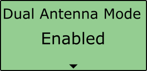
Within the 'Dual Antenna' menu, select 'Dual Antenna Mode', scroll to 'Enable' and select in order to see the full dual antenna system menu.
 |
 |
 |
 |
Antenna Separation
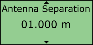
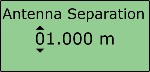
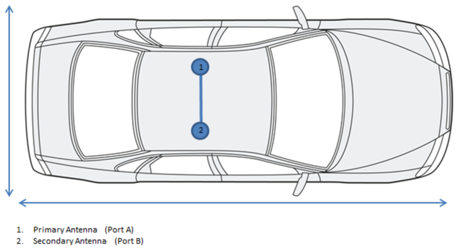
The most important factor for dual antenna testing is the correct configuration of the separation distance between the two antenna centre points. This allows the VB3iD/ VB3iDR to acquire and maintain dual antenna lock. The physical separation distance between the two antennas should be measured as accurately as possible, and entered in to the Separation option of the Dual Antenna menu.
To provide consistent reference, the two antennas should be aligned with the gold antenna connectors pointing in the same direction. This then allows a connector-to-connector physical reference measurement to be made.
Where possible, antennas should be placed on a level plane. The measured distance between the antennas should be the 2D distance between the antennas as viewed from above. It is not the straight-line distance between the antennas, regardless of the mounting angle.
 |
 |
|
 |
Note: Whenever the physical antenna separation is altered, this should be changed accordingly within VBOX Manager.
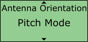
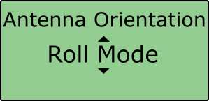
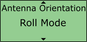
Roll Mode (optional)
The VB3iD/VB3iDR allows the user to separately test roll and pitch measurements during their testing. By default, the VB3iD/VB3iDR will be setup for Pitch determination. If the user wishes to setup their antennas across the width of the car to measure roll angle, then the 'Roll Mode' option must be toggled within the 'Antenna Orientation' menu. To toggle between Pitch Mode and Roll Mode, press on the menu, scroll to the required option and then press again.
 |
 |
|
 |
Align Antennas
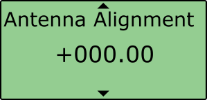
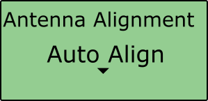
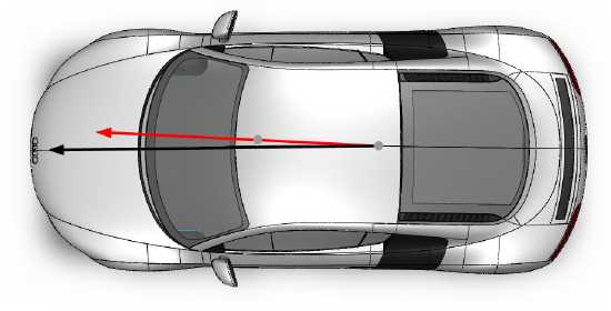
To measure the slip angle with the most precision, try and get the alignment of the antennas as close as possible to the centreline of the vehicle. Any residual errors in this alignment can be removed using the 'Auto Align' feature available in VBOX Manager.
 |
 |
|
The calibration process requires the driver to drive in a straight line for a short period of time, whilst maintaining a constant speed, greater than 25 km/h.
|
 |
 |
 |
Selecting the 'Clear' option will remove any offset applied to the slip channel. |
|

Note: You must have dual antenna lock to be able to perform this calibration.
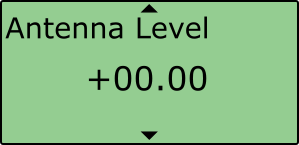
Level Antennas
The Pitch measurement uses the relative height difference between the antennas to calculate the Pitch Angle relative to the ground. If the roof of your vehicle is not perfectly flat in relation to the ground, then this will show up as a Pitch offset. You can automatically remove any offset by performing the 'Auto Level' feature available on VBOX Manager.
Note that any existing antenna level offset from a previous setup should be removed by using the 'Clear' function. This should be completed before the Auto Level.
It is recommended that you perform the Auto Level on a flat, level section of road.
 |
 |
Selecting the 'Clear' option will remove any offset applied to the pitch channel. |
|

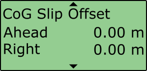
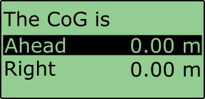
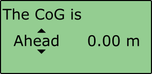
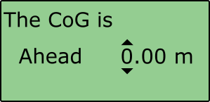
Slip Angle Translation
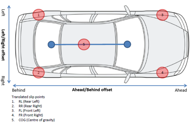
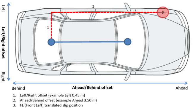
In Dual Antenna mode you may wish to take slip measurements from other locations on the vehicle, for instance the centre of gravity or slip over the wheels. This can be set using the Slip Translation function in VBOX Manager. The five additional locations are set using Ahead/Behind and Left/Right offsets from the primary antenna location (antenna 1 in the picture below).
VB3iD/VB3iDR - IMU assistance: When an IMU module is connected to the VB3iSL, the yaw rate channel will be used in the calculated slip channels, as the signal to noise ratio is much lower than the GPS derived yaw rate. Therefore no extra noise is added during the slip translation process.
 |
 |
 |
 |
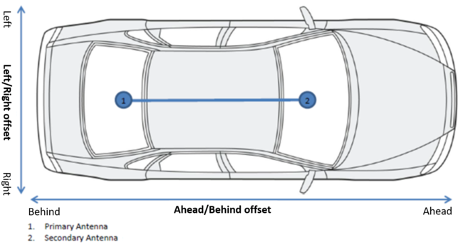
In section 1 on the diagram below there is a Left offset between the primary antenna and the target area for slip measurement. Same again for section 2, there is an Ahead offset. These offsets will need to be applied by VBOX Manager.
Each calculated slip point will require two offsets, Ahead/Behind and Left/Right for the VBOX to calculate the channels correctly. Note: If the primary antenna moves, the offsets will need to be measured again, for example swapping between a pitch and roll setup.