VB3i PIN OUTS

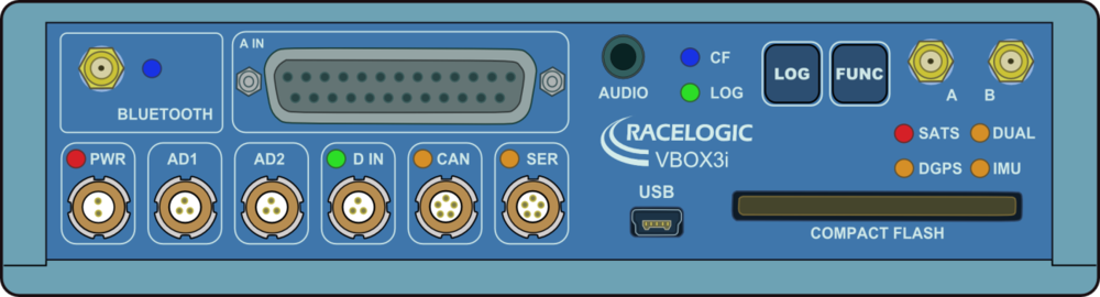
Front View of VBOX 3i RTK (v1-v2)
Connector 1 - POWER (2-pin Lemo)
| PIN | I/O | Function | Connector | ||||
|---|---|---|---|---|---|---|---|
| 1 | I | Power + |  |
||||
| 2 | I | Ground |
Connector 2 - AD 1 (3-pin Lemo)
One Analogue and One Digital Output
| PIN | I/O | Function | Connector | ||||
|---|---|---|---|---|---|---|---|
| 1 | O | Isolated Analogue Out 1 (0 to 5 V) | 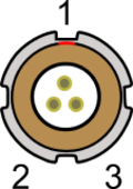 |
||||
| 2 | O | Digital Out 1 (0 to 5 V) | |||||
| 3 | O | Analogue Ground | |||||
| Shell | O | Digital Ground |
Connector 3 - AD 2 (3-pin Lemo)
One Analogue and One Digital Output
| PIN | I/O | Function | Connector | ||||
|---|---|---|---|---|---|---|---|
| 1 | O | Isolated Analogue Out 2 (0 to 5 V) | |
||||
| 2 | O | Digital Out 2 (0 to 5 V) | |||||
| 3 | O | Analogue Ground | |||||
| Shell | O | Digital Ground |
Connector 4 - D IN (3-pin Lemo)
| PIN | I/O | Function | Connector | ||||
|---|---|---|---|---|---|---|---|
| 1 | I | Ground | |
||||
| 2 | I | Digital Input 2 - Logging on/off (0 to 5 V - 14 V tolerant) | |||||
| 3 | I | Digital Input 1 - Brake Trigger (0 to 5 V - 14 V tolerant) |
Connector 5 - CAN (5-pin Lemo)
| PIN | I/O | Function | Connector | ||||
|---|---|---|---|---|---|---|---|
| 1 | O | RS232 Tx - PORT A (± 12 V) | 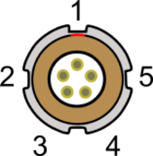 |
||||
| 2 | I | RS232 Rx - PORT A (± 12 V) | |||||
| 3 | I/O | CAN High - PORT B | |||||
| 4 | I/O | CAN Low - PORT B | |||||
| 5 | O | +V Power (Same as Power +) |
Connector 6 - SERIAL (5-pin Lemo)
| PIN | I/O | Function | Connector | ||||
|---|---|---|---|---|---|---|---|
| 1 | O | RS232 Tx - PORT A (± 12 V) | |
||||
| 2 | I | RS232 Rx - PORT A (± 12 V) | |||||
| 3 | I/O | CAN High - PORT B | |||||
| 4 | I/O | CAN Low - PORT B | |||||
| 5 | O | +V Power (Same as Power +) |
Connector 7- Antenna A
| PIN | I/O | Function | Connector | ||||
|---|---|---|---|---|---|---|---|
| Center | N/A | RF Signal/Power for active antenna |  |
||||
| Chassis | N/A | Ground |
Connector 8 - Antenna B
| PIN | I/O | Function | Connector | ||||
|---|---|---|---|---|---|---|---|
| Center | N/A | RF Signal/Power for active antenna |  |
||||
| Chassis | N/A | Ground |
Connector 9 - Analogue Input Connector
VBOX 3i RTK (v2)
| PIN | I/O | Function | Connector | ||||
|---|---|---|---|---|---|---|---|
| 1 | I | Isolated Channel 1 + (1.8 M Ohms input impedance) | 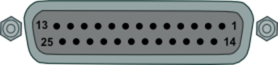 |
||||
| 2 | I | Isolated Channel 1 – (1.8 M Ohms input impedance) | |||||
| 3 | I | Isolated Channel 2 + (1.8 M Ohms input impedance) | |||||
| 4 | I | Isolated Channel 2 – (1.8 M Ohms input impedance) | |||||
| 5 | I | Isolated Channel 3 + (1.8 M Ohms input impedance) | |||||
| 6 | I | Isolated Channel 3 – (1.8 M Ohms input impedance) | |||||
| 7 | I | Isolated Channel 4 + (1.8 M Ohms input impedance) | |||||
| 8 | I | Isolated Channel 4 – (1.8 M Ohms input impedance) | |||||
| 9-13 | N/C | N/A | |||||
| 14 | O | Vbatt (Equal to Input Voltage. 200 mA) | |||||
| 15 | O | Ground | |||||
| 16 | O | 5 V Out (5 V ± 2 %. 350 mA) | |||||
| 17 | O | Ground | |||||
| 18-25 | N/C | N/A |
VBOX 3i RTK (v1)
| PIN | I/O | Function | Connector | ||||
|---|---|---|---|---|---|---|---|
| 1 | I | Isolated Channel 1 + (1.8 M Ohms input impedance) | |
||||
| 2 | I | Isolated Channel 1 – (1.8 M Ohms input impedance) | |||||
| 3 | I | Isolated Channel 2 + (1.8 M Ohms input impedance) | |||||
| 4 | I | Isolated Channel 2 – (1.8 M Ohms input impedance) | |||||
| 5 | I | Isolated Channel 3 + (1.8 M Ohms input impedance) | |||||
| 6 | I | Isolated Channel 3 – (1.8 M Ohms input impedance) | |||||
| 7 | I | Isolated Channel 4 + (1.8 M Ohms input impedance) | |||||
| 8 | I | Isolated Channel 4 – (1.8 M Ohms input impedance) | |||||
| 9-13 | N/C | N/A | |||||
| 14 | O | Vbatt (Equal to Input Voltage. 100 mA) | |||||
| 15 | O | Ground | |||||
| 16 | O | 5 V Out (5 V ± 2 %. 350 mA) | |||||
| 17 | O | Ground | |||||
| 18-25 | N/C | N/A |