Inputs/Outputs - VBOX 3i RTK (v3-v4)

Analogue Inputs
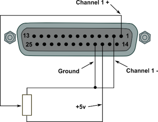
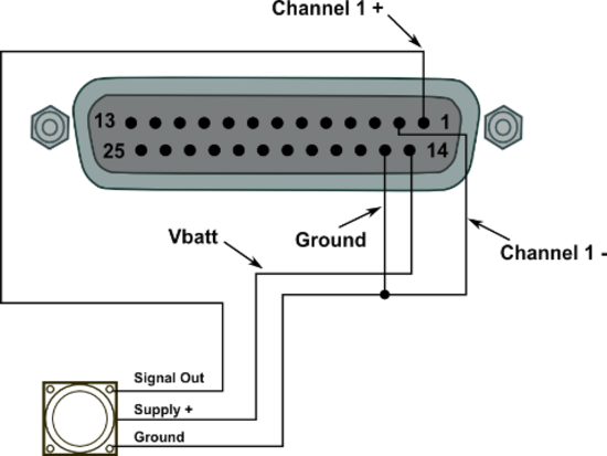
For PIN outs of the Analogue Input Connector click here.
The VBOX 3i contains four differential 24 bit analogue input channels with a maximum sample rate of 500 Hz. Each channel has its own dedicated analogue to digital (A/D) converter with all four channels being sampled synchronously to each other. The voltage range of the input channels is ±50 V. Note that, unlike the ADC03 module, the analogue channels in the VBOX 3i are not electrically isolated from each other.
The analogue input connector also contains voltage outputs that can be used to power external sensors. These are a Vbatt connection which is equal to the VBOX input voltage level and a 5 V DC out connection which is equal to 5 V ±2%.
- V3 units: The 5 V out connection is internally protected by 350 mA thermal fuse.
- V4 units: The 5 V out connection is electrically isolated, allowing for up to 120 mA of current to be drawn.
The Vbatt connection is internally protected by a thermal fuse at 300 mA
A screw-terminal connector block is available as an option for easy connection of signal pins.
 |
 |
Note: A 25 W D-sub to 4 W BNC adaptor block is available through your VBOX distributor, part number RLVBACS054
Using VBOX Setup software, logging of the analogue channel data can be switched on or off. It is also possible to change the name of each input channel and configure scale and offset values for calibration of sensors. A scale value of 1 and offset of 0 correspond to a channel reading in V DC. This means that the value stored on the compact flash card for the channel will also be in volts. When using a sensor such as a load cell, it may be desirable to store a reading in kg. In this case, changing the scale and offset to suit the sensor data sheet allows the data stored onto the compact flash to be in kg. When changing settings for an analogue channel using VBOX Setup software, a live data view of the current channel is shown. The value shown is the value after scale and offset is applied and can therefore be used to aid sensor calibration.
Note: The 5 V regulated output on pin16 is only good for VBOX power supply voltages >8.5 V

AD channel properties
500 Hz logging
VB3i has the ability to log 4x analogue channels at 500 Hz. With this feature enabled, the file sizes will increase as a result.
The 500 Hz analogue logging functionality is only fully supported when Fixed CAN timing is used.
When loading the VBO file into VBOX Test Suite, ensure you are running the very latest version as older versions are not compatible with 500 Hz data.
Within VBOX Setup, the 500 Hz option is available within the 'Logging' settings, as shown below.
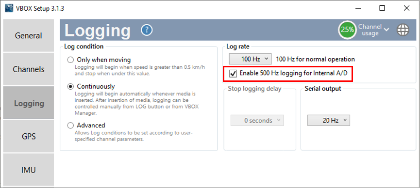
VBOX Setup A/D 500 Hz
Digital Inputs
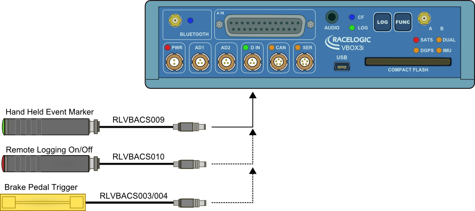
The ‘D IN’ connector contains the two digital inputs for the VBOX 3i. Digital input 1 is also referred to as the brake trigger input. This input is connected to an event capture input on the GPS engine. This captures precisely the trigger event time (10 ns resolution) for use in brake distance calculation. The trigger event time is logged and used to correct the measured brake stop distance to the exact point at which the trigger was pressed.
A hand-held event marker is also available to allow the user to record marker events in the VBOX 3i data file.
A remote logging on/off switch is also available for ease of use and when the front panel switch is not accessible.
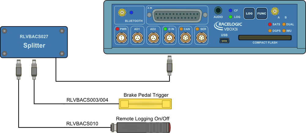
Two digital inputs devices can be connected to the VBOX 3i with the use of an additional splitter box, as shown in the image below.
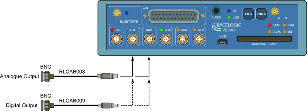
Analogue and Digital Outputs
The AD1 and AD2 connectors each have 1 analogue voltage and 1 digital output. The digital output on connector AD2 is a frequency/pulse output corresponding to velocity. The pulse per meter range is adjustable in software. The digital output on connector AD1 is a simple on/off state output. This digital output can be associated with any of the data channels being logged by the VBOX. A threshold level can be set for the selected data channel where a true condition gives a 5 V output and a false condition gives a 0 V.
i.e. Data channel –Speed, threshold 40 km/h. When speed is >40 output = 5 V, speed, 40 output = 0 V.
A hysteresis and tolerance value can also be associated to this condition.
The default function of this digital output is to indicate the current logging status of the VBOX.
The analogue outputs on connectors AD1 and AD2 are both user configurable. For example, analogue output 1 could be configured to output velocity while analogue output 2 might be configured to output lateral acceleration. The voltage range of both analogue outputs is 0 to 5 V DC.