02 Front Panel - VBOX 3i RTK
ConnectorsYou can find more information about the different inputs and outputs here. |
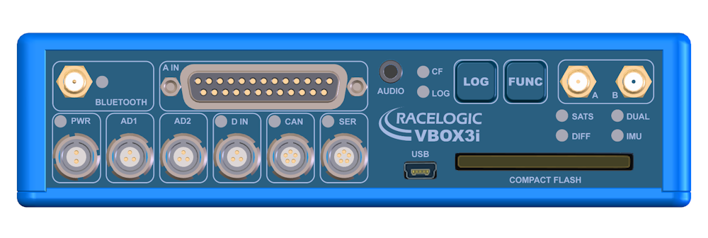
| BLUETOOTH | VBOX 3i units come equipped with a Bluetooth radio. This allows for configuration of the VBOX unit remotely, along with the remote output of real-time VBOX serial data, at the full 100 Hz data rateto any Bluetooth capable PC or data logger. |
| A IN |
This is the analogue input connector. Each of the four analogue input channels on a VBOX 3i unit has a dedicated analogue converter. Data is recorded from each channel simultaneously. The analogue input connector also provides two power outputs that may be used for driving sensors. |
| PWR | This is the power connector. VBOX 3i units can accept a supply voltage between 7 and 30 V DC. |
| AD1 | The AD1 port has 1 analogue voltage and 1 digital output. The digital output is a simple on/off state output that can be associated with any of the data channels being logged by the VBOX. You can set a threshold level for the selected data channel, where a true condition gives a 5 V output and a false condition gives a 0 V output. You can also associate hysteresis and tolerance values with this condition. The default function of this digital output is to indicate the current logging status of the VBOX. |
| AD2 |
The AD2 port has 1 analogue voltage and 1 digital output. The digital output is a frequency/pulse output that corresponds to velocity. You can adjust the pulse per metre range in the VBOX Setup. The voltage range of the analogue output is 0 to 5 V DC. |
| D IN |
The ‘D IN’ connector contains the two digital inputs for the VBOX 3i RTK.
|
| CAN* | The secondary RS232 port is used for connection to a Telemetry Radio module allowing the reception of Differential GPS (DGPS) data for local correction from a Racelogic Local DGPS base station, or Moving Base solution. The secondary RS232 port is located in the connector marked CAN on the VBOX 3i front panel. |
| SER* |
The primary RS232 port is used for all communication between the VBOX 3i unit and a laptop PC. The primary port is marked SER on the front panel. Note: Due to the max bandwidth being 115200, live data transfer of all channels is limited to 20 Hz. 50 Hz should only be used to transmit standard GPS channels and Solution Type, and 100 Hz can only transmit Sats, Time, Speed, and Trigger Event Time. Logging too many channels at too high a rate will cause drop-outs and loss of data. For maximum accuracy, you should log tests performed at a GPS sample rate above 20 Hz to compact flash and do a post-process analysis. |
| AUDIO | VBOX 3i units can record audio tags synched with a set GNSS timestamp, with an accuracy of 0.5 seconds. |
| USB |
VBOX 3i units include a USB 2.0 connection that you can use to configure your VBOX unit and output real-time serial data at the full 100 Hz data rate. |
| ANTENNA A | The primary antenna connector. |
| ANTENNA B | The secondary antenna connector. |
*You can configure the function of the CAN and SER ports with VBOX Setup and swap the Racelogic Bus profile. The Racelogic CAN bus is used for connected Racelogic modules or displays. The Vehicle CAN bus (VCI) is for use by third-party CAN equipment, whether you are logging to or from the VBOX. For dual use of RS232 and CAN from one of the sockets you will need to use a 5-way Lemo splitter (RLVBACS024).
|
IMPORTANT Power supplied to external Racelogic CAN modules through the CAN or SER cables is at the same voltage as the input power supply. When you are using Racelogic external CAN modules (e.g. MFD or ADC03), you must make sure that the VBOX 3i supply voltage does not exceed 15 V DC. |
LEDs
| CF | Indicates that the unit is writing to the Compact Flash card. |
| LOG | Indicates that the unit is capturing data to the CF card. |
| SATS | Indicates the number of satellites being tracked. |
| DUAL | Indicates whether dual antenna mode is enabled/disabled and that the antenna lock is fixed. |
| DIFF | Indicates the DGPS status. |
| IMU | Indicates the IMU integration and initialisation status. |
| BLUETOOTH | Indicates that communication has been initialised and that Bluetooth connection has been confirmed. |
| PWR | Indicates whether the unit is powered and ready to use or not. |
| D IN | Indicates activated/triggered event marker input. |
| CAN | Indicates that expected incoming CAN data has been decoded properly and is being logged. |
| SER | Indicates incoming serial traffic and that incoming CAN data has been decoded and is being logged. |
| You can find the full description of the different behaviours of the LEDs here. | |