03 Front Panel – VBOX IISL – Dual Antenna

Display Screen Overview
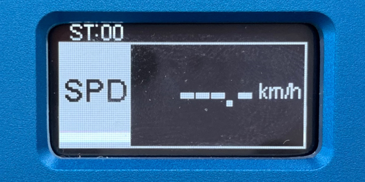
The screen will display data when the VBOX IISL - Dual Antenna is operating. It also displays all the menus you need to configure the VBOX IISL via the front panel controls.
On start-up, the display screen will show the unit’s firmware version and the current offset value.
During normal operation, the display screen displays Speed (mph or km/h) and Slip Angle, as well as the number of satellites that the VBOX IISL - Dual Antenna has locked on to, there are also three status indicators at the top of the display. Scroll left or right ( ‘◄’ and ‘►’), to display the Pitch or Roll Angle instead of the Slip Angle.
 |
| GPS Status | Display notifications | ||
|---|---|---|---|
| Left Position | Middle Position | Right Position | |
| No Satellite Lock | - | SAT (flashing) | RTK (flashing) |
| Full Lock | OK | - | - |
| Antenna A only SAT Lock | - | RTK (flashing) | RTK (flashing) |
| Antenna A and B SAT Lock | - | RTK | RTK (flashing) |
If you have enabled a DGPS mode, this is indicated by the middle indicator light with one of the following messages.
| DGPS Mode | Light Status |
|---|---|
| WAAS, SBAS or EGNOS Differential correction | WAAS |
| 40 cm Differential correction from Base station | 40 cm |
Logged Filename:
When you insert an SD card, the filename of the logged file appears on the screen while the data is being logged.
Front Panel Buttons
You can configure VBOX IISL - Dual Antenna units by using the front panel buttons. This makes it possible to configure your unit without the need for a computer. Alternatively, you can configure it in the VBOX Setup Software.
From the main screen, press the ’■’ button to enter the configuration screen.
Note: Entering the configuration screen will cause the VBOX to stop logging to the SD card. When in continuous logging mode, please ensure that the ’■' button is pushed prior to removing the SD card to avoid data loss.
Once in the configuration screen, press the ‘◄’ and ‘►’ buttons to highlight the next or previous choice in any menu, and press ’■’ to select the highlighted option. Most Main menus contain sub-menus, for example, the Settings and Setup Antennas menus contain separate menus for each parameter.

Main Menu
| SETTINGS | Press ’■’ to enter the VBOX general settings menu. |
|---|---|
| COLDSTART | Press ’■’ to perform a GPS coldstart. |
| MODE | Press ’■’ to change the mode of operation between VBOX module mode and Stand Alone mode. Then press ’■’ to confirm. |
| SETUP ANTENNAS | Press ’■’ to enter the antenna configurations menu. This menu contains separate sub-menus for pitch antenna and roll antenna pairs. |
| SMOOTHING | Press ’■’ to edit the smoothing levels of the Lat acc and Long acc channels, Slip, Pitch and Roll. |
| OUTPUTS | Press ’■’ to configure the digital and analogue outputs. |
| EXIT | Press ’■’ to exit the setup menu and save the settings in the electrically erasable programmable read-only memory (EEPROM). |
Settings Menu
| UNITS |
Press ’■’ to change the displayed Velocity units. Then press ’■’ to confirm. KMH, MPH or Knots |
|---|---|
| APPLICATION | Press ’■’ and use the ‘◄’ and ‘►’ buttons to select between AUTOMOTIVE or MARINE mode. Marine mode causes the box to display the Pitch, Roll and Slip angles as Trim, Heel and Leeway Angles on the built-in screen and also as channel names inside the logged file. |
| USB MODE | Press ’■’ and use the ‘◄’ and ‘►’ buttons to select whether the USB port is assigned to Serial data mode or Card reader mode. |
| CAN MODE |
Press ’■’ and the ‘◄’ and ‘►’ buttons to choose between the following modes: To connect any external CAN modules to the input of the VBOX IISL - Dual Antenna. To connect Racelogic CAN modules to the input or output of the VBOX IISL - Dual Antenna. |
| LOG OPTIONS |
Press ’■’ to enter the Log Options Menu. In this menu, you can set the Logging Mode and Log rate. |
| SERIAL RATE | Press ’■’ and use the ‘◄’ and ‘►’ buttons to select a serial data rate. The maximum serial rate is equal to the Log rate. |
| GPS | Press ’■’ to enter the GPS configuration Menu. This is the menu where you can configure the Kalman Filter, Dynamic Mode and DGPS mode. |
| TIME OFFSET | Press’ the ‘◄’ and ‘►’ buttons to set an Time offset to align the VBOX time to the user's local time. |
| BACK | Press ’■’ to go back to the Main menu. |
Setup Antennas (Pitch Antenna)
| SEPARATION |
Press ’■’ and use the ‘◄’ and ‘►’ buttons to change the antenna separation. Press ’■’ to confirm. The range is 0.5 – 5.0 m (in steps of 0.1 m). |
|---|---|
| LEVEL |
Press’■’ and then use the ‘◄’ and ‘►’ buttons to enable or disable the LEVEL option. With the LEVEL set to YES the RTK lock is more resilient. The maximum ROLL or PITCH in this mode should be 10 degrees. |
| SWAP ANTENNAS |
Set to ‘ON’ to allow the primary Antenna A to be mounted ahead of the Secondary Antenna B. Default is ‘OFF’. Then press ’■’ to confirm. |
| SLIP OFFSET | Press ’■’ to enter the Slip offset sub-menu. In this sub-menu, you can calculate and apply or clear the Slip offset. |
| PITCH OFFSET | Press ’■’ to enter the Pitch offset sub-menu. In this sub-menu, you can calculate and apply or clear a Pitch offset. |
| BACK | Press ’■’ to go back to the Main menu. |
Smoothing Menu
| LAT ACC |
Press ’■’ and use the ‘◄’ and ‘►’ buttons to change the amount of smoothing applied to the calculated Lateral Acceleration output. Press ’■’ to confirm. 0.0 – 5.0 (in steps of 0.1) |
|---|---|
| LONG ACC |
Press ’■’ and use the ‘◄’ and ‘►’ buttons to change the amount of smoothing applied to the calculated Longitudinal Acceleration output. Press ’■’ to confirm. 0.0 – 5.0 (in steps of 0.1) |
| SLIP |
Press ’■’ and use the ‘◄’ and ‘►’ buttons to change the amount of smoothing applied to the Slip angle channel. Press ’■’ to confirm. 0.0 – 5.0 ((in steps of 0.1) |
| PITCH |
Press ’■’ and use the ‘◄’ and ‘►’ buttons to change the amount of smoothing applied to the Pitch angle channel. Press ’■’ to confirm. 0.0 – 5.0 (in steps of 0.1) |
| ROLL |
Press ’■’ and use the ‘◄’ and ‘►’ buttons to change the amount of smoothing applied to the Roll angle channel. Press ’■’ to confirm. 0.0 – 5.0 (in steps of 0.1) |
| BACK | Press ’■’ to go back to the Main menu. |
Outputs: Digital Setup Menu (Channel 1 and 2)
| OUTPUT | Press ’■’ and use the ‘◄’ and ‘►’ buttons to associate either of the following channels SPEED, SLIP, PITCH, ROLL, LAT ACC and LONG ACC to the Digital output. Press ’■’ to confirm. |
|---|---|
| PULSES PER METER | This setting is only available when output is set to SPEED.
Press ’■’ and use the ‘◄’ and ‘►’ buttons to set the number of pulses per revolution. Press ’■’ to confirm. 0.1 – 120 (in steps of 0.1) |
| MAX SPEED |
This setting is only available when output is set to SPEED. Press ■’ and use the ‘◄’ and ‘►’ buttons to set the maximum Speed. Press ’■’ to confirm. (in steps of 0.1) (in steps of 1 km/h) |
| MAX VALUE |
This setting is only available when the output is set to LAT ACC, LONG ACC, PITCH, SLIP or ROLL. Press ’■’ and use the ‘◄’ and ‘►’ buttons to set the maximum value of that channel. Press ’■’ to confirm. 0 – 180o (in steps of 1o) for Slip 0 – 90o (in steps of 1o) for Pitch 0 – 90o (in steps of 1o) or Roll 0.5 – 2 g (in steps of 0.1 g) for LAT ACC 0.5 – 2 g (in steps of 0.1 g) for LONG ACC |
| MAX FREQUENCY | This setting is only available when output is set to LAT ACC, LONG ACC, PITCH, SLIP or ROLL.
Press ’■’ and use the ‘◄’ and ‘►’ buttons to set the maximum frequency for the digital output. Press ’■’ to confirm. 1 – 50 kHz (in steps of 0.1 kHz) |
| TEST | Press ’■’ and use the ‘◄’ and ‘►’ buttons to set a test value that the Digital output will simulate. Press ’■’ to quit. |
| EXIT | Press ’■’ to exit the setup menu and save the settings in EEPROM. |
Outputs: Analogue Setup Menu (Channel 1 and 2)
| OUTPUT | Press ’■’ and use the ‘◄’ and ‘►’ buttons to associate either of the following channels SPEED, SLIP or PITCH, ROLL, LAT ACC and LONG ACC to the Analogue output. Press ’■’ to confirm. |
|---|---|
| VALUE @ +5V |
Press ’■’ and use the ‘◄’ and ‘►’ buttons to set the value to represent +5 V. Press ’■’ to confirm. 1 – 400 km/h (in steps of 1 km/h) for SPEED -179o to 180o (in steps of 1o) for SLIP -89o to 90o (in steps of 1o) for PITCH -89o to 90o (in steps of 1o) for ROLL -1 to 2 g (in steps of 0.1g) LAT ACC -1 to 2 g (in steps of 0.1g) LONG ACC |
| VALUE @ 0V |
This setting is only available when the output is set to SPEED. Press ’■’ and use the ‘◄’ and ‘►’ buttons to set the velocity to represent 0 V. Press ’■’ to confirm. 0-399 km/h (in steps of 1 km/h) |
| VALUE @ -5V |
This setting is only available when the output is set to LAT ACC, LONG ACC, PITCH, SLIP or ROLL. Press ’■’ and use the ‘◄’ and ‘►’ buttons to set the value to represent -5 V. Press ’■’ to confirm. -2 to 1 g (in steps of 0.1g) LAT ACC -2 to 1 g (in steps of 0.1g) LONG ACC -180o to 179o (in steps of 0.1o) for SLIP -90o to 89o (in steps of 1o) for PITCH -90o to 89o (in steps of 1o) for ROLL |
| TEST | Press ’■’ and use the ‘◄’ and ‘►’ buttons to set a test value that the Analogue output will simulate. Press ’■’ to quit. |
| EXIT | Press ’■’to exit the setup menu and save the settings in EEPROM. |
GPS Menu
| DYNAMIC MODE |
Press ’■’ and the ‘◄’ and ‘►’ buttons to select the required dynamics. HIGH DYNAMICS - Essential for brake testing and lane changing maneuvers. NORMAL - Select this for standard testing – speed, distance, etc. LOW DYNAMICS - Select this for route mapping and similar tests where the level of the dynamic response is not important. |
|---|---|
| DGPS MODE |
Press’■’ and the ‘◄’ and ‘►’ buttons to select the DGPS settings. OFF – No DGPS applied – standard position accuracy 3 m CEP. WAAS – position accuracy 1.8 m CEP. 40CM – position accuracy 40CM*. 20CM** – position accuracy 20CM*. |
| KALMAN FILTER |
Press ’■’ and the ‘◄’ and ‘►’ buttons to set the Kalman filter options. POSITION LEVEL – Smoothes the positional data. VELOCITY LEVEL – Smoothes the velocity data. |
| BACK | Press’■’ to return to the GPS menu. |
*Note: These accuracies are only achievable in conjunction with a DGPS base station.
**Note: The 20 cm mode requires a separate upgrade file (RLVBUP30) that you can purchase by contacting Racelogic Support.
Factory Reset
If you want to perform a factory reset on the unit, for example, if the unit is not functioning correctly, press and hold the ’■’ and ‘►’ buttons with power supplied to the VBOX IISL - Dual Antenna. The front panel display will show an 'updating eeprom' message, notifying you of the process.