VBOX Sigma has various connectors/sockets on the top and bottom of the unit, along with an OLED display and buttons.
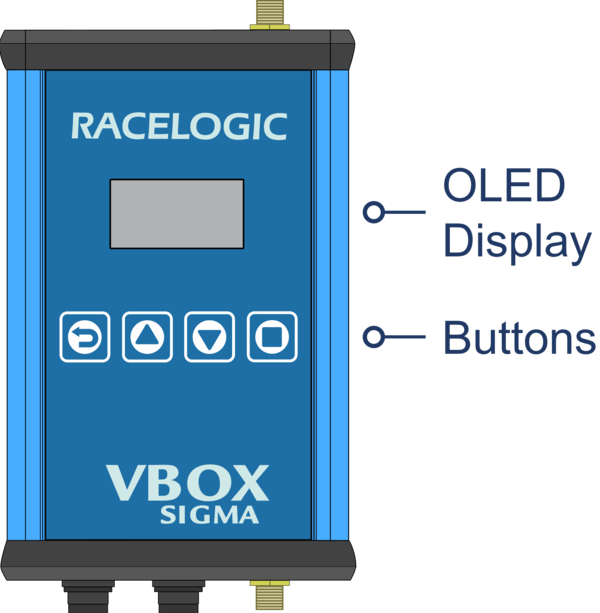
The front panel of the unit contains an OLED screen which displays status and connection information. Three screens are available to view, more information on these is available here.
Pressing the Back Button on the left will return to the Home Display Screen if currently on another display screen.
The Up and Down Buttons are used to navigate between the three different display screens, more information on these is available here.
Pressing the Square Button on the right will start/stop logging irrespective of the Logging Strategy selected within the VBO Log Settings area of the Wi-Fi hotspot configuration interface. More information on logging is available here. If this button is pressed without an SD card inserted. a 'No SD Card' message will be displayed.
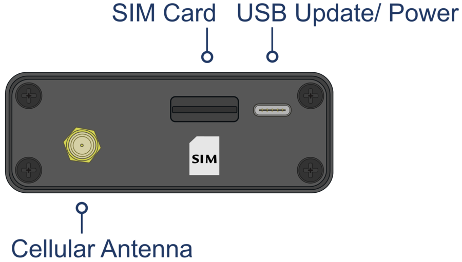
The top of the unit houses a slot for inserting a Standard SIM card if are intending on using the internal 4G modem to connect to the NTRIP server, and a USB socket for updating the unit using the supplied USB cable. If you are connecting to another GNSS receiver rather than a VBOX, the USB socket can also be used to power the unit if power isn't available via the Hirose connection (more information on USB power is available here).
An SMA connector is also included for attaching the supplied cellular antenna (ANTMSTUBSMAM).
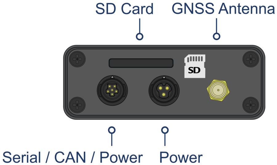
The bottom of the unit houses 2 Hirose connectors, the centre one can be used to supply power to the unit via the supplied RLCAB010H cable. The other connector can be used to connect to a VBOX or other GNSS system to supply RTK correctional messages via CAN.
There is also a an SD card slot for logging data and an SMA connector for attaching the supplied GNSS antenna (RLACS308).
Further connector pin information is available here.