BSD - Multi-Target (Static Base)
- Last updated
- Save as PDF

Multiple Vehicle Targets
This mode facilitates the ability for vehicle separation parameters to be calculated at the Subject vehicle with respect to two Target vehicles.
This system consists of a VB3iSL-RTK in each Target vehicle and a VB3iSL-RTK in the Subject vehicle.
NOTE: It is not possible to operate in Duplex mode with multiple Target vehicles.
High accuracy of the vehicle separation calculations is made possible by the use of a Static Base Station.
The Target VBOX (tracked vehicle) will also log the normal GPS data to a .vbo file, so that the files from each VBOX can be compared in the VBOX Tools Graph screen or VBOX Test Suite Chart screen. This is useful to see the relative positions.
Configuration of the VBOX’s is done through VBOX Manager (RLVBFMAN).
Hardware configuration
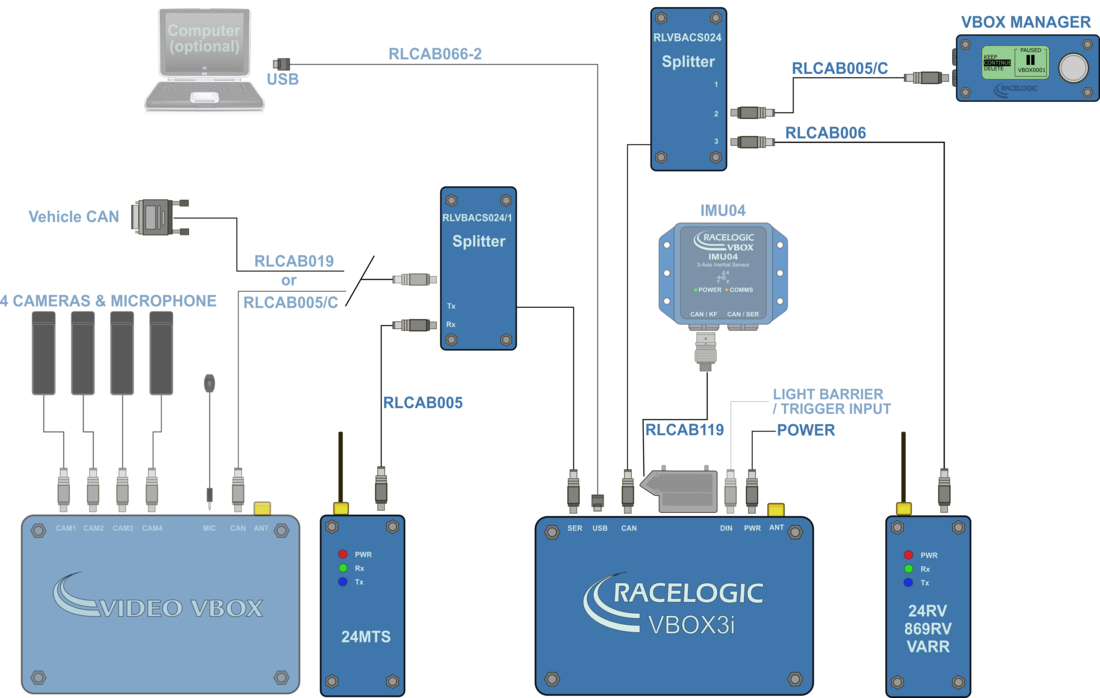
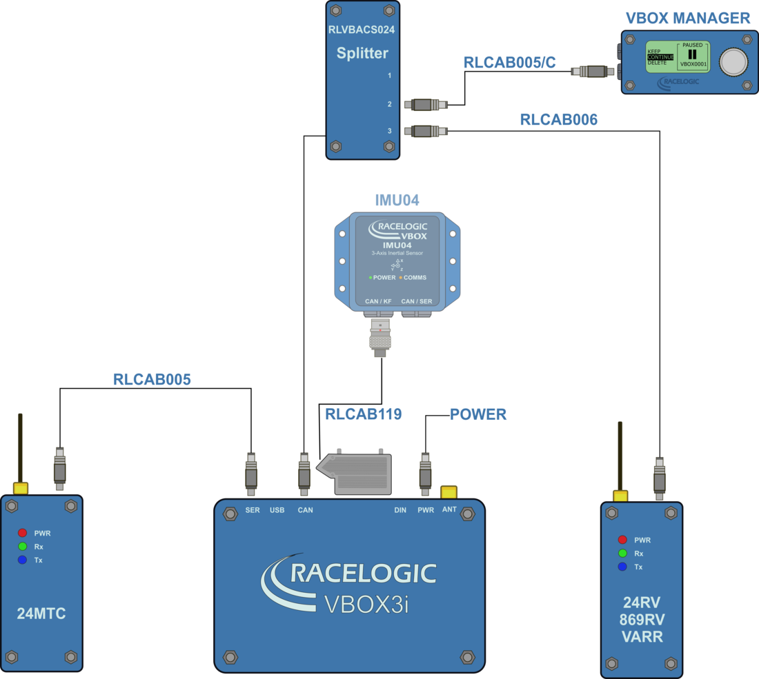
Testing with two target vehicles requires the installation of three VBOX ADAS systems, one in the Subject Vehicle and one in each Target Vehicle. The following diagrams show the recommended hardware configuration for each vehicle. The items greyed out are not essential but many customers may find them beneficial.
Connection between the VB3i and computer should be made via USB or Bluetooth to ensure optimum performance.
Please ensure that all vehicle antennas are correctly positioned and connected.
VBOX Configuration
Target Vehicle 1This guide assumes the use of a Base Station. |
| 1. Connect VBOX Manager to the VBOX in Target Vehicle 1. |
| 2. Enter the setup menu of VBOX Manager. |
| 3. Select the 'VBOX' option. |
|
4. Select 'LOG RATE' and set the rate to '100 Hz', then select 'BACK' to return to the 'VBOX' setup menu.
|
|
5. Select 'DYNAMICS' and set the dynamic mode to 'NORMAL', this Dynamics mode is best for ADAS tests, return to the 'VBOX' setup menu.
|
|
6. Select 'DGPS' and set the DGPS mode to the same 2 cm mode that the Base Station is set to, return to the 'VBOX' setup menu.
|
|
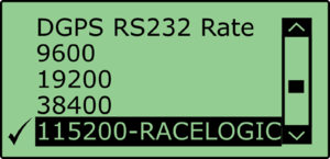
7. Select 'DGPS RS232 Rate' and select the appropriate settings for your radios, return to the VBOX setup menu. Note: To ensure that the VBOX receives the DGPS correction signal, the correct RS232 rate must be set. All Racelogic blue boxed radios use 115200 kbit/s, Satel grey boxed radios use either 19200 kbit/s or 38400 kbit/s. |
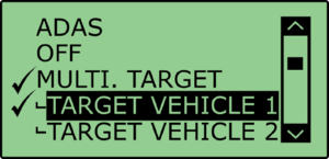
8. Return to the main setup menu and select the 'ADAS' option, then select 'MULTI. TARGET' mode..png?revision=1) |
|
9. Select 'TARGET VEHICLE 1' and return to the 'ADAS' setup menu.
|
Target Vehicle 21. Connect VBOX Manager to the VBOX in Target Vehicle 2. |
| 2. Repeat steps 2 – 8 in section 'Target Vehicle 1' above. |
|
3. Select 'TARGET VEHICLE 2' and return to the 'ADAS' setup menu.
|
Subject Vehicle1. Connect VBOX Manager to the VBOX in the Subject Vehicle. |
| 2. Repeat steps 2 – 8 in section ‘Target Vehicle 1' above. |
.png?revision=1) |
ADAS Radio LinkFor Multiple-Target mode, you must use radio modems programmed with different configuration scripts. It is not possible to use the normal ADAS link radios. The Radios at each TARGET VBOX need to be set to CLIENT mode and paired to the singular ADAS radio at the subject vehicle. The radio at the subject vehicle needs to be set to SERVER and BROADCAST mode. |
|
When the 2.4 GHz modems are connected correctly the 'SER' light on the Subject VBOX will illuminate, indicating the reception of a serial data stream. |
|
 |
.jpg?revision=1) |
RTK DGPS Configuration for Multi-Target
Static BasePlease refer to the ‘Base Station user guide’ for guidance on Base Station installation and setup. |
|
DGPS ModesVBOX 3i and Base Station supports the use of three different RTK DGPS modes; each mode will provide 2 cm accurate solution. Racelogic recommends the use of CMR or RTCMv3 as these modes have less radio bandwidth requirement, which should lead to more reliable RTK lock. |
|
RTK Status Indication1. To confirm the Base Station telemetry units have been set up correctly the following should apply:
|
|
|
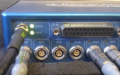
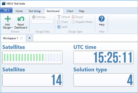
2. Confirm that both VBOX units are now in RTK 'Fixed' DGPS status, indicated by the following: |
|
'DIFF' LED on the VBOX front panel is illuminated green. |
A VBOX Tools live window set to Solution Type shows 'RTK FIXED'. |
|
A VBOX Test Suite live Workspace window set to Solution type shows '4' (RTK fixed). |
Pre-Test Configuration
Setting The Contact Points |
After selecting the Subject Vehicle in either the multi or single target modes, the user can set the contact points by entering the ‘CONTACT POINTS' Menu.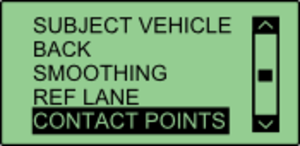.png?revision=1) |
|
In this menu, it is possible to define contact points for either the ‘Subject Vehicle’ or ‘Target Vehicle’. You can manually configure up to 2 contact points by entering a numerical offset, or you can set up to 24 contact points by using a GPS antenna. |
Manually Entering Contact Points
.png?revision=1) |
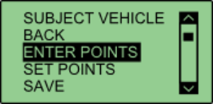
Select either 'SUBJECT VEHICLE' or 'TARGET VEHICLE' in the contact points menu. Select 'ENTER POINTS'. |
.png?revision=1) |
Select 'NO. OF POINTS'. |
.png?revision=1) |
This menu allows the user to select whether 1 or 2 contact points are to be specified. The current number of selected points is highlighted with a tick next to the number. Selecting a different number will move that tick to that number. Select 'BACK' once completed. |
.png?revision=1) |
Select 'POINT 1' to specify first contact point. |
.png?revision=1) |
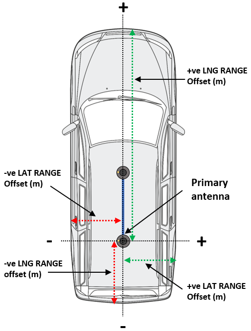
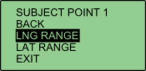
This menu allows the user to translate the Primary antenna point (or IMU if IMU integration is enabled) to a desired reference point on the vehicle. This is done by entering a numerical longitudinal (‘LNG RANGE’) and lateral (‘LAT RANGE’) offset value. |
.png?revision=1) |
Selecting ‘LNG RANGE' allows the user to enter a longitudinal offset, with a forward offset being POSITIVE and a rearward offset being NEGATIVE. Pressing ‘APPLY’ will store the value. |
.png?revision=1) |
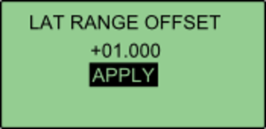
Selecting ‘LAT RANGE' allows the user to enter a lateral offset, with a rightwards offset being POSITIVE and a leftwards offset being NEGATIVE. Pressing ‘APPLY’ will store the value. Select 'BACK' to return to the previous menu. |
.png?revision=1) |
If the user selected 2 contact points in NO. OF POINTS, POINT 2 will be displayed on the menu. Select ‘POINT 2' and repeat the above process. Repeat this process to define the other vehicle. |
Setting Up To 24 Contact Points
|
| First, connect a ground plane antenna to the VBOX. Select either 'SUBJECT VEHICLE' or 'TARGET VEHICLE' in the contact points menu. Select 'SET POINTS'. .png?revision=1) |
| Using the survey pole, move the antenna to the desired contact point on the vehicle. Ensure there is a fixed RTK solution and select 'SET POINT'. If successful, VBOX Manager will display 'POINT 1 SAVED'. |
If there is no RTK fix, the point will not be saved and VBOX Manager will display 'POINT 1 NOT SET, NOT RTK FIXED'..png?revision=1) |
| To set the next point, move the antenna to another desired point of contact and repeat the process. Repeat this process until all the desired points are set, or a limit of 24 is reached. Once all the desired points are set, move the antenna to the location of antenna A and select 'SET ANT A'. .png?revision=1) |
| Then move the antenna to the location of Antenna B and select 'SET ANT B'. This process can be repeated to define the other vehicle. If multiple points have been set on either vehicle, the calculated ADAS parameters (range, angle etc) will always reference the nearest surveyed point. .png?revision=1) |
Saving Vehicle Contact Points |
After the required contact points have been surveyed, it is possible to save these points to the compact flash card by selecting 'SAVE'..png?revision=1) |
This allows the user to either overwrite a previously saved file, or create a new save file using the '{CREATE NEW}' option..png?revision=1) |
Selecting the '{CREATE NEW}' option will display an alpha numeric scroll wheel where the user can enter the desired file name..png?revision=1) |
.png?revision=1) |
Loading Vehicle Points |
Select either 'SUBJECT VEHICLE' or 'TARGET VEHICLE' in the contact points menu. Then select 'LOAD'..png?revision=1) |
This will bring up a list of all previously saved files, which the user can select to load..png?revision=1) |
.png?revision=1) |
Setting a reference lineA reference line is used to provide a very stable heading reference for the calculation of a noise free Lateral Difference Channel (LatDif-tg1) - see parameter definitions for more detail. |
| 1. Under the 'MULTI. TARGET' option within the 'ADAS' menu, navigate to 'SUBJECT VEHICLE' and select 'REF LINE'. |
| 2. Move the vehicle to the first nominated point along a straight line that runs perfectly parallel to the test track (a good method for this is to get the outside front and rear tyres perfectly aligned on a marked straight line). |
|
3. Within the 'REF LINE' menu, select 'SET PNT 1'. |
| 4. Move the vehicle to a distance at least 100 m along the straight line, ensuring that the car is re-aligned. |
|
5. Select 'SET PNT 2'.
|
|
|
SmoothingIf the box is set into twin antenna mode, the smoothing menu will not be present as the calculations will run off of the True heading provided by the twin antenna lock. It is recommended that if user intends to set multiple points on the car, they enable the dual antenna. There are two configurable variables linked to heading smoothing; ‘Smoothing Distance’ and ‘Speed Threshold’. Due to the nature of the vehicle separation measurement and calculation process many channels are derived using the heading of the vehicle which can inherently be noisy. To overcome this heading can be smoothed with a dynamic smoothing routine. |
Smoothing Distance
|
|
Above: Shows the improvement on vehicle heading from using smoothing distance |
Setting A Smoothing Distance |
|
1. Using VBOX Manager, go to the 'ADAS' menu and go to the 'MULTI. TARGET' menu and select 'SUBJECT VEHICLE'.
|
|
2. Select 'SMOOTHING' from the 'SUBJECT VEHICLE' menu. 3. Select ‘SMOOTHING DIST' and enter the smoothing option for the Subject Vehicle, from the options between 0.00 m and 2.00 m.
|
| 4. For typical Vehicle Separation applications we recommend a smoothing distance of 1 m. |
Speed ThresholdDue to the nature of how heading is calculated, even when Smoothing is applied at very low speeds and when the vehicle is stationary the heading channel can become very noisy and unusable, this in turn results in many of the Vehicle Separation channels becoming noisy at low speed and unusable when stationary. This is solved by fixing the heading below a configurable Speed Threshold. |
|
1. To set the speed threshold repeat steps 1 and 2 above, then select 'SPD THRESHOLD' and enter the speed threshold option for the Subject Vehicle.
|
| 2. We recommend a Speed Threshold of 5 km/h. |

.png?revision=1)
.png?revision=1)
.png?revision=1)
.png?revision=1)
.jpg?revision=1)
.png?revision=1)
.png?revision=1)
.jpg?revision=1)

.png?revision=1)
.png?revision=1)
.png?revision=1)