Pass-By Noise with VBOX 3i
Overview
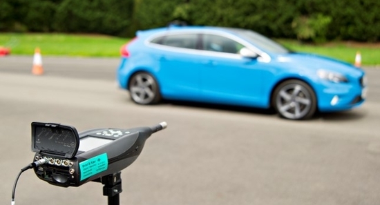
Certification of vehicle noise emissions for passenger vehicles, motorcycles and light trucks is achieved by measuring external sound levels according to procedures defined by international standards such as ISO 362 and the Environmental Protection Agency (EPA).
Racelogic provides Pass-By (or Drive-By) Noise testing equipment to log channels such as engine RPM, vehicle velocity and maximum vehicle exterior noise to the accuracy requirements of this standard. The system can be installed in the vehicle for R51, R117 and R138, allowing the driver to operate the measurement equipment without the need for additional operatives.
Additionally, VBOX Test Suite software has been enhanced to include Pass-By Noise plugins, allowing development programs to be completed to the EPA, ECE R41, ECE R51, ECE R117 and ECE R138 standards, prior to homologation testing.
|
|
|
Test Procedure
The test procedure involves an open-throttle acceleration test and a constant speed test. The tests must be repeated several times to prove a consistent average value, with at least four measurements on each side of the vehicle and for each gear.
Although the test pass criteria are different between EPA, R41, R51, R117 and R138 testing, the test track setups are the same as shown in the Test Setup below.
Acceleration Test
This test requires the driver to apply full throttle between the lines AA’ and BB’. The selection of gear ratio depends on the vehicles acceleration potential as specified in the standard. The test must be repeated several times to prove a consistent average value.
Constant Speed Test
The constant speed test shall be carried out with the same gear(s) as specified in the acceleration test and a constant speed of 50 km/h ±1 km/h between AA’ and BB’. The tests must be repeated several times to prove a consistent average value.
Test Setup
Microphones placed within the test area output to a VBOX Mini Input Module using the DC voltage output of the microphones. The Mini Input Module continuously transmits the converted sound readings to the VBOX 3i GNSS data logger mounted on the test vehicle at 100 Hz using 2.4 GHz Telemetry Radios.
IMPORTANT INFORMATION
- The radios should always have the antenna connected when powered, otherwise they could become damaged.
- The VBOX 3i should be powered before the VBOX Mini Input Module.
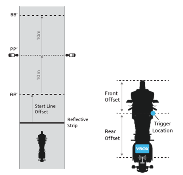
R41 Test Track Layout showing microphone locations (Left) and Laser Trigger installation on test vehicle (Right)
If using laser light, it should be attached to the side of the vehicle under test and a reflective strip is placed a distance before the start test line AA’ to define the start and end lines of the test as shown above.
These offset distances are input into the VBOX Test Suite Pass-by Noise plugins for the analysis to occur. You can use the system in both directions, just install another reflective strip on the other end of the test track so when you drive in the opposite direction it will also trigger. The reflective strip needs to be the same distance away from the start line as your current strip. The vehicle must come to a stop after each pass so the function can be reset.
Instead of using a laser light barrier to trigger the start of the test, a VBOX 3i RTK (VB3iDR) can be used to set the start and finish lines when used with an RTK Base Station or NTRIP solution. This means that the test vehicle doesn’t have to come to a stop between test runs. Find more information about this here.
It is necessary to enter the front and rear vehicle offsets from the laser light trigger or GNSS antenna if using GPS start/finish lines within the VBOX Test Suite Pass-by Noise plugin Edit Data settings. The start of the test is deemed to be when the front of the vehicle passes the start line and the end is when the rear of the vehicle passes the finish line.
If an extension cable for the SLMs is not possible on your test track, then another Mini Input Module and Road Side Telemetry radio position on the opposite side of the track can be used to stream the sound pressure level from the Sound Level Meter to the VBOX. Further information can be found in the R41 and R51/R117/R138 hardware setups as shown below.
Weather station data can also be logged, click here for more information.
Hardware and Software Configuration
|
In terms of hardware layout, the only difference between the layouts for each regulation is that the PC or Tablet can be easily installed inside the vehicle for R51 and R138 Testing instead of on the roadside for R41 Testing. |
 |
R41
Dual Mini Input Modules
Equipment
- 1 x RLVB3i; 100 Hz GPS Data Logger
- 1 x RLACS189; Laser Light Barrier Kit*
- 3 x RLACS333-L; 6 Ah Li-Ion battery pack
- 3 x RLRTMXB2; Vehicle and Roadside Telemetry Radio
- 2 x RLVBMIM01; Mini Input Module
- 2 x RLCAB143; B&K 2250 SLM DC output Cable to Mini Input Module
- 1 x PC or Tablet
- 1 x RLVBDSP03-24; Multi-Function Display is an optional item for R41 Testing
- 2 x RLCAB081; Optional cables if using both an MFD and CAN Input from the test vehicle
- 2 x RLACS252; Rugged roadside equipment case
- 1 x RLACS253; Rugged motorcycle equipment case
- 2 x RLCAB218; Lemo 5W to Lemo 2W socket
*Optional DGPS radio can be used as a substitute for the Laser Light Barrier (RLACS189), but you will need a VB3iDR and RTK Base Station to do this.
Hardware layout
.png?revision=1)
Single Mini Input Modules
Equipment
- 1 x RLVB3i; 100 Hz GPS Data Logger
- 1 x RLACS189; Laser Light Barrier Kit*
- 2 x RLACS333-L; 5 Ah Li-Ion battery pack
- 2 x RLRTMXB2; Vehicle and Roadside Telemetry Radio
- 1 x RLVBMIM01; Mini Input Module
- 2 x RLCAB143; B&K 2250 SLM DC output Cable to Mini Input Module
- 1 x PC or Tablet
- 2 x RLCAB081; Optional cables if using both an MFD and CAN Input from the test vehicle
- 1 x RLACS252; Rugged roadside equipment case
- 1 x RLACS253; Rugged motorcycle equipment case
- 1 x RLCAB218; Lemo 5W to Lemo 2W socket
*Optional DGPS radio can be used as a substitute for the Laser Light Barrier (RLACS189), however, a VB3iDR and RTK Base Station are required.
Hardware layout

R51/R117/R138
Dual Mini Input Modules
Equipment
- 1 x RLVB3i; 100 Hz GPS Data Logger
- 1 x RLACS189; Laser Light Barrier Kit*
- 2 x RLACS333-L; 5 Ah Li-Ion battery pack
- 3 x RLRTMXB2; Vehicle and Roadside Telemetry Radio
- 2 x RLVBMIM01; Mini Input Module
- 2 x RLCAB143; B&K 2250 SLM DC output Cable to Mini Input Module
- 1 x PC or Tablet
- 1 x RLCAB081; Optional cables if using both an MFD and CAN Input from the test vehicle
- 2 x RLACS252; Rugged roadside equipment case
- 2 x RLCAB218; Lemo 5W to Lemo 2W socket
*You can use the optional DGPS radio as a substitute for the Laser Light Barrier (RLACS189) if you have a VBOX 3i RTK unit and an RTK Base Station.
Hardware layout
Note: The hardware setup for R51, R117 and R138 are the same.
.png?revision=1)
Single Mini Input Modules
Equipment
- 1 x RLVB3i; 100 Hz GPS Data Logger
- 1 x RLACS189; Laser Light Barrier Kit*
- 2 x RLACS333-L; 5 Ah Li-Ion battery pack
- 2 x RLRTMXB2; Vehicle and Roadside Telemetry Radio
- 1 x RLVBMIM01; Mini Input Module
- 2 x RLCAB143; B&K 2250 SLM DC output Cable to Mini Input Module
- 1 x PC or Tablet
- 1 x RLCAB081; Optional cables if using both an MFD and CAN Input from the test vehicle
- 1 x RLACS252; Rugged roadside equipment case
- 1 x RLCAB218; Lemo 5W to Lemo 2W socket
*Optional DGPS radio can be used as a substitute for the Laser Light Barrier (RLACS189), however, a VB3iDR and RTK Base Station are required.
Hardware layout
Note: The hardware setup for R51, R117 and R138 are the same.
.png?revision=1)
Sound Level Meter Setup
Configure the SLMs such that LAF sound pressure level is set to the DC output. Using a B&K 2250 Sound level meter, the procedure is as follows:
- Go into the Menu (bottom left of screen).
- Go to 'Setup'.
- Click on 'Output Socket Signal'.
- Set the Source to 'LAF'.
Firmware Upgrade
Load the latest firmware into the Mini Input Module and VBOX 3i from the VBOX Automotive website.
Instructions on how to do this can be found at MIM Firmware Upgrade and VB3i Firmware Upgrade.
Mini Input Module (MIM01) Setup
- Switch the RLCAB005 cable radio connection from the DATA1 to the DATA2 socket.
- Connect the DATA1 socket on the MIM01 to a computer using the RLCAB001 cable to the computer's serial port (USB-serial adapter may be required).
- To eliminate any disruption with connection, ensure that the VBOX 3i you are using is either not powered or not connected to its radio.
- Install the latest version of VBOX Setup, which can be downloaded here and open the software.
- When the computer has made a connection to the MIM using VBOX Setup, click on Settings and depending on how many Mini Input Modules you are using, select the following:
- Single Mini Input Module - Select Sound Level Meter(s) only within the Operation mode as shown below.
- Dual Mini Input Modules - Within the Operation mode, one module must be set as Sound Level Meter(s) only and the other as Sound Level Meter(s) and Weather Station only.
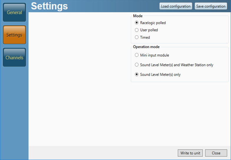
- Click the Write to unit button.
VBOX 3i Setup
- Connect to a computer via Bluetooth, an RLCAB001 cable to the SER input and the computer's serial port (USB-serial adapter may be required), or via an RLCAB066-2 cable to one of the computer's USB ports.
- Open VBOX Setup software.
- When the computer has made a connection to the VBOX 3i using VBOX Setup. Click on Channels, then Internal Pass-By Noise and the first tab as shown below.
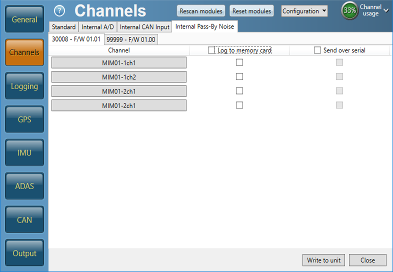
- If using only Sound Level Meters, click on MIM01-2ch1, the channel name and units can be changed. For B&K 2250 SLM units, set the scaling to 50 and click OK. Repeat again for MIM01-2ch2.
.png?revision=2)
- Check Log to memory card and Send over serial boxes as shown below.
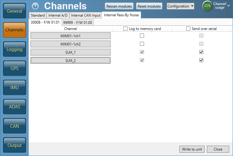
- Ensure the Serial Output is set as 20 Hz to match the radios.
- Click the Write to unit button.
- Close VBOX Setup. Both RX/TX LEDs should be flashing on the radios, this demonstrates that the Road Side equipment and the VBOX 3i are communicating correctly with each other.
Detailed instructions on how to use the Pass-By Noise Software Plug-ins are available within in the VBOX Test Suite EPA, R41, R51, R117 and R138 user manual pages.

.png?revision=3)