MFD Touch - Target Screen
The TARGET screen is selectable from the ADD/REMOVE screen. It contains a target gauge with 3 supporting numerical elements. The units used depend on what is selected in the Settings menu.
.png?revision=1)
Target Element
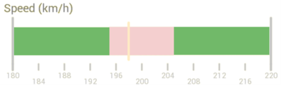
The Target Graph gauge element is located on the bottom of the screen, it provides a visual representation of a selected parameter (speed by default).
_Red_Highlight.png?revision=1)
You can configure the gauge by pressing and holding or double-tapping on it. This will open up the TARGET GRAPH SETTINGS menu.
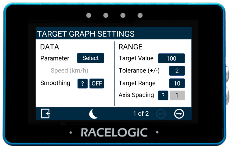 Screen 1 |
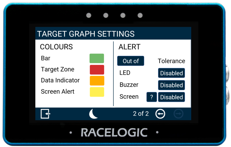 Screen 2 |
There are 2 Target Graph settings screens available: DATA/RANGE and COLOURS/ALERT. You can toggle between these screens by pressing the Forward or Back arrows at the bottom right of the screen or by swiping left or right. You can change the settings by pressing the corresponding button next to an option.
To return to the parameter screen, select the Exit button in the bottom left corner.
Note: If you have an SD card inserted, it will remember the settings values after each power cycle.
Data
Parameter
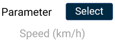
The gauge parameter is set as speed by default, but you can change it by pressing the Select button to open the parameter list. You can assign any data parameter that is available from the connected VBOX to the Target Graph (apart from UTC Time, Longitude, Latitude, Solution Type, Trigger, Filename, Logging Status, Memory Used, and
KF Status).
Note: The currently selected parameter data source is highlighted in blue and the currently selected parameter is displayed in grey in the options list.
-_highlighted_option_750px.png?revision=1) Data Source Menu |
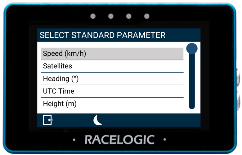 Standard Parameter Menu |
Use the scroll bar on the right-hand side of the selection screen to navigate through the options and press the desired parameter to confirm your selection.
Return to the settings screen by pressing the Exit button in the bottom left corner.
You can find a list of available parameters here.
Note: If a previously selected CAN channel parameter is no longer available, the values for that parameter will display as zero or nil. The parameter reference name will be greyed out and 'MISSING PARAMETER' will flash in the header of the screen.
Smoothing

You can smooth the Target data if required. The input value determines the number of previous data samples used to smooth the displayed data. It does not affect any of the performance results or the logged data of the connected unit.
To enable smoothing, press the current value (off by default) and use the presented keypad to enter the number of previous data samples you would like to use within the display smoothing.
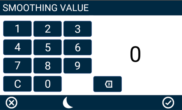
Smoothing Value Keypad Example
Save your selected value by pressing the Confirm button in the bottom right corner. Press the Cancel button in the bottom left corner to return to the Settings screen without saving.
Notes:
- The maximum input value is 99.
- Smoothing can introduce a slight delay to the displayed value.
Range
Target Value
The target value will be located at the centre of the gauge. You can define this by pressing the value box and using the presented keypad to define the required value (set as 240 by default).
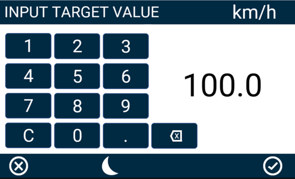
Target Value Keypad Example
Save your selected value by pressing the Confirm button in the bottom right corner. Press the Cancel button in the bottom left corner to return to the Settings screen without saving.
Notes:
- The maximum input value is 99999.
- The minimum input value is -99999 (when the signed parameter is selected, otherwise 0).
- One decimal place resolution is available to values under 10000.
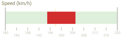
Tolerance (+/-)
Define the tolerance (target zone) displayed on either side of the target value. You can define the colour used for this zone (red by default) by pressing on the Target Zone option in the Colours settings area.
The value is set to 2 by default, but you can press the value box and use the presented keypad to define the required value. By using the default +/- tolerance value of 2 as an example, for a target value of 100, the target zone would be from 98 – 102.
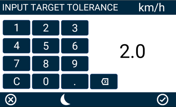
Target Tolerance Keypad Example
Save the selected value by pressing the Confirm button in the bottom right corner. Press the Cancel button in the bottom left corner to return to the Settings screen without saving.
Notes:
- The maximum input value is 9999.
- The minimum input value is 0.1.
- One decimal place resolution is available to values under 1000.
Target Range
This option defines the range of the background bar (set as 10 by default). You can change the colour used for this bar (green by default) by pressing on the Bar option in the Colours settings area.
To change the range value, press the value box and use the presented keypad to select the required value. Using the default range value of 10 as an example, for a target value of 100, the bar range would be from 95 – 105.
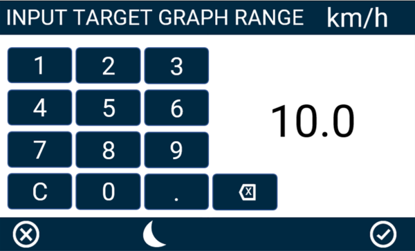
Target Range Keypad Example
Save the selected value by pressing the Confirm button in the bottom right corner. Press the Cancel button in the bottom left corner to return to the Settings screen without saving.
Notes:
- The maximum input value is 9999.
- The minimum input value is double the Target Value Tolerance setting.
- One decimal place resolution is available to values under 1000.
Axis Spacing
The Axis Spacing value tells you how much spacing there is between each gauge increment marker. This value changes depending on the Target Range Value.
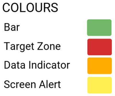
Colours
|
Bar: Set the colour of the background bar.
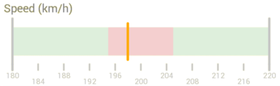
Target Zone: Set the colour of the Target Zone, which is configured using the Tolerance Value.
Data Indicator: Set the colour of the Data Indicator which is the current value.
Screen Alert: Set the colour of the Screen Alert. Find more information on this is below. |
 |
To change any of the colours used, press the current colours and use the presented RGB sliders to define your new colours. The area to the left of the sliders provides a colour preview.
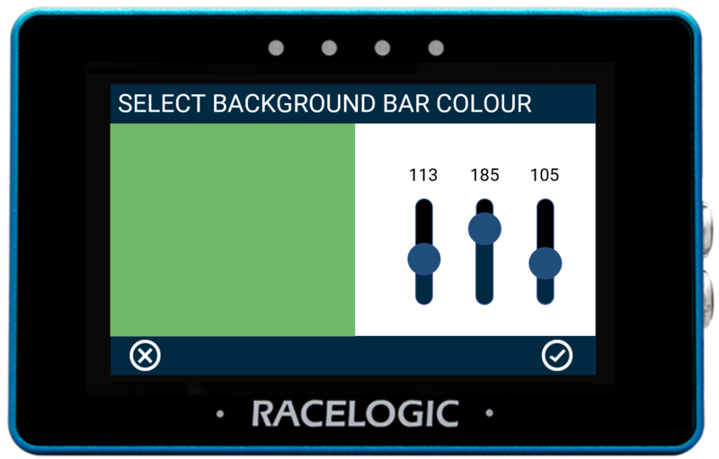
Background Bar Colour Configuration Example
Save your colour selection by pressing the Confirm button in the bottom right corner. Press the Cancel button in the bottom left corner to return to the Settings screen without saving.
Note: If you enable Night Mode, it will reset user defined colours.
Alert
Tolerance
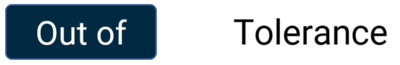
This option allows you to define whether the alert is for a value Out of (default) or Within the Defined Target Value Tolerance. Press the button to change the option.
LED
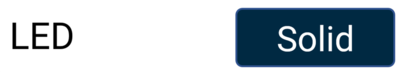
Select this setting to enable a solid or flashing visual alert when the Defined Target Value Tolerance is met. Press the button to cycle through the options. The device will preview the setting with the 4 red LEDs across the top of the unit.
Buzzer

Select to enable an audible alert when the Defined Target Value Tolerance is met. The MFD Touch will beep when this setting is enabled.
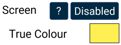
Screen
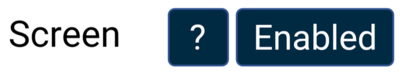
You can enable a screen alert when the Defined Target Value Tolerance is met. When the value has been achieved, the background of the parameter will change colour.
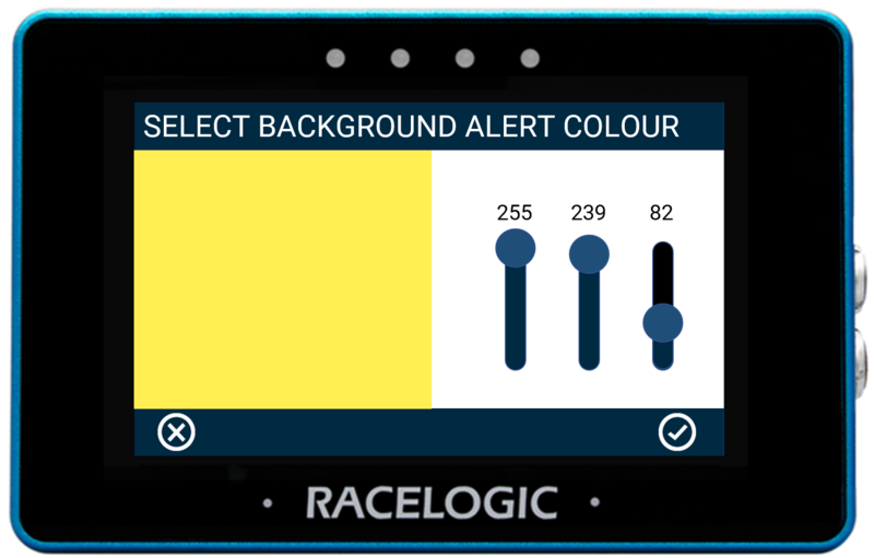
You can change the background alert colour by pressing the current Screen Alert colour (yellow by default) in the Colours area and using the presented RGB sliders to define your new colour. The area to the left of the sliders provides a colour preview.
 Screen Alert Colour Configuration Example |
_Yellow_Screen_Alert.png?revision=1) Screen Alert Example |
Numerical Elements
The 3 numerical elements are located on the top of the screen and include Speed, Satellites and Heading parameters by default.
_Numerical_Highlight.png?revision=1)
You can configure each parameter by pressing and holding or double-tapping the existing parameter area. This will open up the NUMERICAL SETTINGS menu.
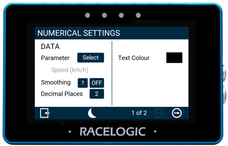 Screen 1 |
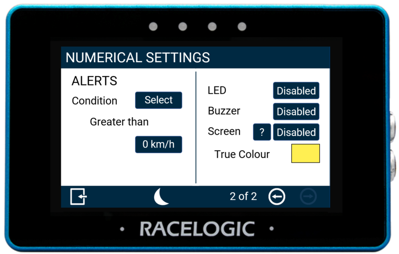 Screen 2 |
There are 2 numerical settings screens available: DATA and ALERTS. You can toggle between these screens by pressing the Forward or Back arrows on the bottom right of the screen or by swiping left or right. You can change the settings by pressing the corresponding button next to an option.
To return to the parameter screen, select the Exit button in the bottom left corner.
Note: If you have an SD card is inserted, it will remember the settings values after each power cycle.
Data
Parameter
You can change a parameter by pressing the Select button to open the Data Source menu, where you can choose from Standard, VBOX CAN, Decel Test, and Accel Test parameters. You can assign any data parameter that is available from the connected VBOX along with any MFD Touch calculated test results to the selected numerical element.
Note: The currently data source is highlighted in blue and the currently selected parameter is displayed in grey on the options list.
Data Source Menu |
Standard Parameter Menu |
Use the scroll bar on the right-hand side of the selection screen to navigate through the options and press the desired parameter to confirm your selection.
Return to the settings screen by pressing the Exit button in the bottom left corner.
You can find a list of available parameters here.
Smoothing
You can smooth the displayed live speed values. The input value determines the number of previous data samples used to smooth the displayed data. It does not affect any of the performance results, or the logged data of the connected unit.
To enable smoothing, press the current value (off by default) and use the presented keypad to enter the number of previous data samples you would like to use within the display smoothing.
Smoothing Value Keypad Example
Save the selected value by pressing the Confirm button in the bottom right corner. Press the Cancel button in the bottom left corner to return to the Settings screen without saving.
Notes:
- The maximum input value is 99.
- Smoothing can introduce a slight delay to the displayed value.
- The setting will be greyed out and disabled if the numerical parameter being configured is UTC Time, Longitude, or Latitude.
Decimal Places
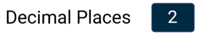
Configure how many decimal places are used to represent the nominated data for the selected numerical element.
Available options include 0, 1, 2 and 3. The default setting is 2, with the exception of integer only channels which including Satellites, Trigger Test Number, Decel Test Number, and UTC Time which do not have any decimal points. Tap the buttons to change the decimal places used.
Text Colour
You can define the text colour of the numerical element data. Press the current colour (black by default) and use the presented RGB sliders to define your new colour. The area to the left of the sliders provides a colour preview.
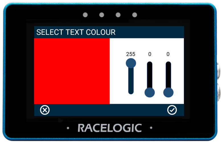 Text Colour Configuration Example |
_Red_Numerical_Text.png?revision=1) Text Colour Change Example |
Save your colour selection by pressing the Confirm button in the bottom right corner. Press the Cancel button in the bottom left corner to return to the Settings screen without saving.
Notes:
- A text colour change applies to the data text only, it does not apply to the parameter label.
- If you enable Night Mode, it will reset user defined text colours.
Alerts
Condition
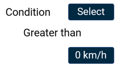
This option allows you to define an alert condition. Press the Select button to cycle through the available conditions: Equal To, Not Equal To, Less Than, Less Than or Equal To, Greater Than (default), Greater Than or Equal To, Between,or Not Between. You can then define the alert condition value(s) by pressing the value box and using the keypad presented.
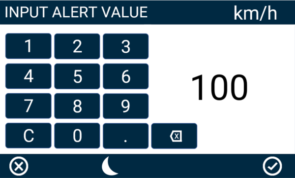
Alert Value Keypad Example
Save the selected value by pressing the Confirm button in the bottom right corner. Press the Cancel button in the bottom left corner to return to the Settings screen without saving.
Note: The setting will be greyed out and disabled if the numerical parameter being configured is UTC Time, Longitude, or Latitude.
LED
Select to enable a solid or flashing visual alert when the Defined Alert Condition is met. Press the button to cycle through the options. The device will preview the setting with the 4 red LEDs across the top of the unit.
Note: The setting will be greyed out and disabled if the numerical parameter being configured is UTC Time, Longitude, or Latitude.
Buzzer
Select to enable an audible alert when the Defined Alert Condition is met. The MFD Touch will beep when this setting is enabled.
Note: The setting will be greyed out and disabled if the numerical parameter being configured is UTC Time, Longitude, or Latitude.
Screen
You can enable a screen alert when the Defined Alert Condition is met. When the value is achieved, the background of the parameter will change colour.
Note: The setting will be greyed out and disabled if the numerical parameter being configured is UTC Time, Longitude, or Latitude.
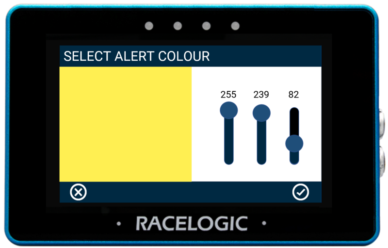
To change the background alert colour, press the current colour (yellow by default) and use the presented RGB sliders to define your new colour. The area to the left of the sliders provides a colour preview.
 Screen Alert Colour Configuration Example |
_Numerical_Screen_Alert.png?revision=1) Screen Alert Example |
Save your colour selection by pressing the Confirm button in the bottom right corner. Press the Cancel button in the bottom left corner to return to the Settings screen without saving.
Note: If you enable Night Mode, it will reset user-defined alert colours.