05 - VBOX Speed Sensor Configuration

The VBOX Speed Sensors have default settings applied so that you can use them straight out of the box. You can, however, also configure the settings for your Speed Sensor, by using the VBOX Setup software, which you can download here.
Software connection
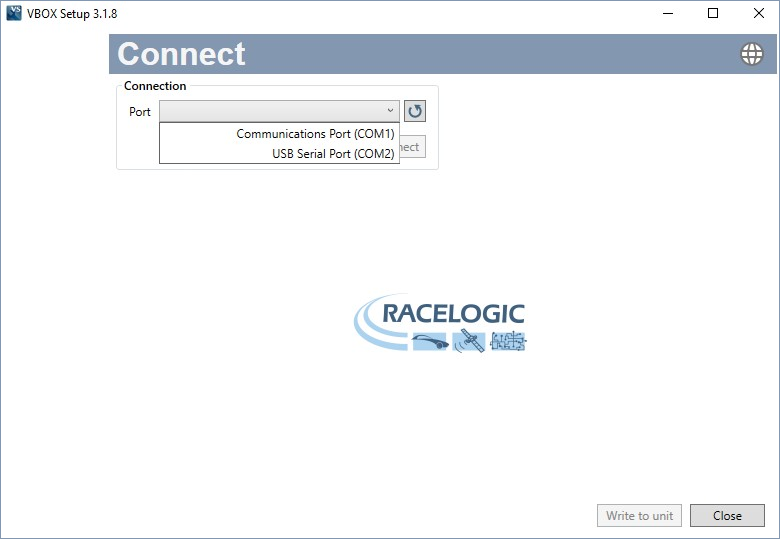 |
Use the drop-down menu in the Connection area on the Connect screen to select the COM port you have connected the Speed Sensor to. When you have connected a COM port, the radio button under the drop-down menu will turn green and say 'Connected'. Click on the Disconnect button to disconnect the currently connected COM port.
Note: You may see an auto-detect message if the baud rate has been changed from the default value. Select ‘Yes’ to allow the different baud rates to be scanned.
Setup options
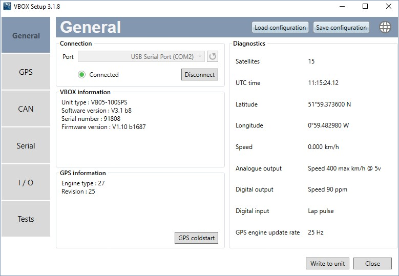
General Tab
 |
| Menu name/ button |
Description/function | |
|---|---|---|
|
Connection |
This menu contains the Selected com port drop-down, along with a refresh button and a Disconnect button. | 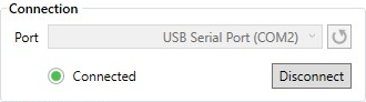 |
| VBOX Information | This area will provide information about the unit type, software version, serial number and installed firmware version currently being used. | 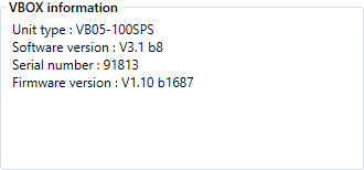 |
| GPS Information | Technical information about the GPS engine in the connected unit. | 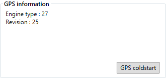 |
| GPS Coldstart |
This feature clears the almanac stored in the GPS engine. You should only use this when your device is struggling to gain SAT lock. |
 |
| Load/Save configuration | You can save the configuration you set up to a file for later use and you can load a saved configuration file if you have a suitable one already set up. Note that these files should be in the .sscfg format. |  |
| Language | Change the operating language. |  |
|
Diagnostics |
Displays live GNSS data and basic current setup. |  |
|
Write to unit |
After making changes to the setup, you must click the Write to unit button to upload the settings to the Speed Sensor. |  |
| Close | When you have completed your setup or you want to cancel your setup without writing anything to the unit, click on Close to close the setup window. |  |
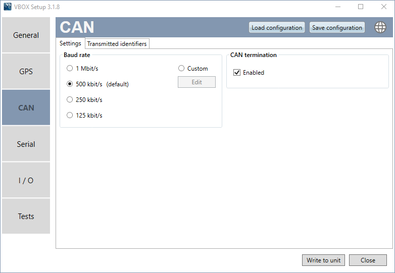
CAN Tab
Settings
 |
| Menu name/ button |
Description/function | |
|---|---|---|
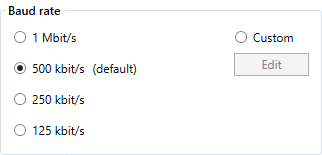
| Baud Rate |
The software has 4 common baud rate values: 1 Mb/s, 500 kb/s, 250 kb/s or 125 kb/s. You can also select a custom baud rate. |
 |
| CAN termination | You can enable or disable the internal CAN termination resistance here. | 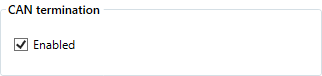 |
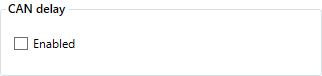
| CAN delay |
Only available on 100 Hz units. Enabling this feature will fix the CAN latency at 15.5 ms. Note: While the unit still transmits all channels, it will stabilise Speed on CAN ID 302 when this feature is enabled. You can find more information about the CAN delay function here. |
 |
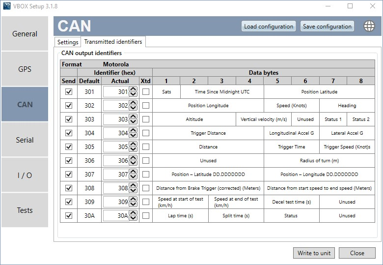
Transmitted Identifiers
 |
| Menu name/ button |
Description/function | |
|---|---|---|
| Send | You can select if a CAN message is switched on/off by ticking or unticking this box for the corresponding message. |  |
| Identifier (hex) | These columns allow you to modify the CAN IDs transmitted by the Speed Sensor. Default values are the Racelogic standard ID’s of 0x301, 0x302, 0x307, etc. In the Actual column, you can change the ID value, and by ticking the Xtd box behind the Actual ID value you can extend the identifier format from standard 11-bit to extended 29-bit. | 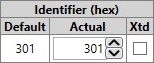 |
| Data bytes | These are the different channels available under the different messages. You can find more information about the CAN output of the Speed Sensors here. | 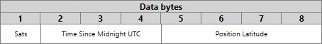 |
GPS Tab
 |
| Menu name/ button |
Description/function | |
|---|---|---|
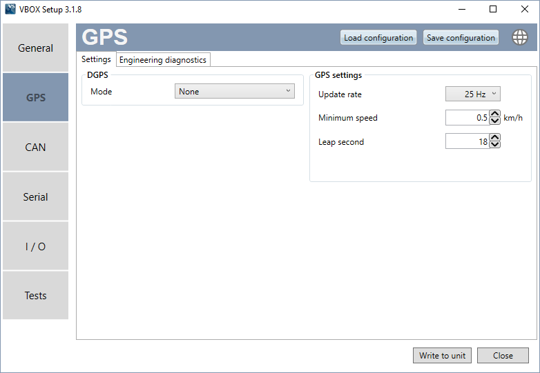
| DGPS Mode | This feature gives you the option to enable differential GPS: None – Differential GPS is off. SBAS – SBAS differential corrections are received from the nearest Geo-stationary GPS-SBAS satellite. |
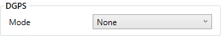 |
| GPS Settings |
This is where you can change the update rate of the GPS engine and set a minimum speed output value if required. |
 |
Serial Tab
 |
| Menu name | Description/function | |
|---|---|---|
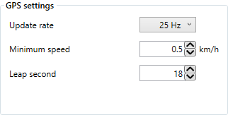
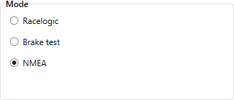
| Mode | This selects which format the VBOX Speed Sensor will output the Serial data in. NMEA message format is the only user configurable setup. Racelogic: For online connection with VBOX Test Suite. |
 |
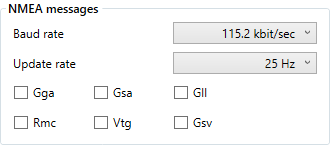
| NMEA Messages | If the NMEA message format is selected, the following options become available. Baud Rate: The required serial baud rate can be selected from this drop-down menu. Update Rate: You can change the update rate of the NMEA messages by using this drop-down menu. Message Selection: You can select or deselect NMEA messages for transmission by checking and un-checking the boxes next to each message type. Click here for VBOX Speed Sensor Serial Output protocols |
 |
I/O Tab
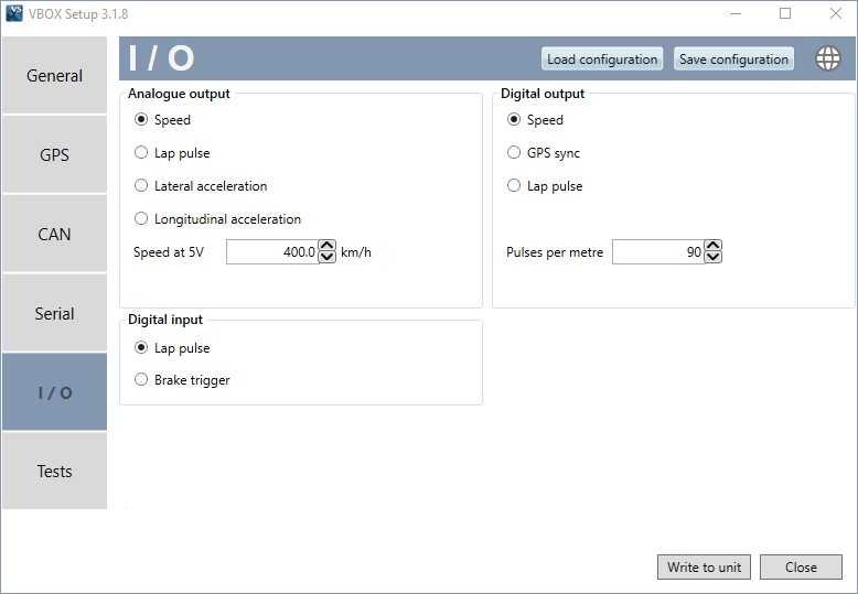 |
Analogue output
| Menu name/ button |
Description/function | |
|---|---|---|
| Speed | Enter the maximum for the speed range you wish to measure. The default speed is set to 400 km/h. The maximum speed at 5 V can be in the range 10 to 1000 km/h. | 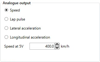 |
| Lap Pulse | When this option is enabled the VBSS will output a 5 V pulse when a Start/Finish line is crossed. The duration of the pulse in milliseconds can be adjusted by entering a different value. The polarity of the pulse can be changed to either a rising or falling pulse by clicking the ‘Polarity’ button. | 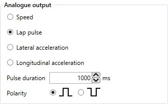 |
| Lateral / Longitudinal Acceleration | Select the range you wish to use from the drop-down menu. | 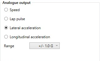 |
Digital Output
| Menu name/ button |
Description/function | |
|---|---|---|
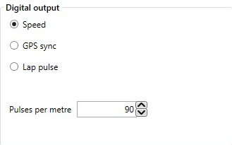
| Speed |
The speed output is configured by changing the number of pulses per metre. Default = 90 pulse per metre => 25 Hz per km/h. |
 |
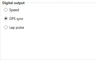
| GPS Sync | Selecting this option outputs a pulse every second, which is synchronised to the GPS clock. Note: This feature is an optional extra which is not available by default. A GPS engine update is required to allow this to work correctly. |
 |
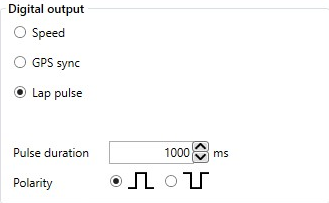
| Lap Pulse |
When this option is enabled the VBSS will output a 5 V pulse for 300 ms when a Start/Finish line is crossed. The duration of the pulse in milliseconds can be adjusted by entering a different value. The polarity of the pulse can be changed to either a rising or falling pulse by selecting the marker next to the desired image. |
 |
Digital Input
You can use the Digital Input and a switch to program the position of virtual lines with the VBOX Speed Sensor. This lets you set Start/Finish lines and Split lines. You can also use the Digital Input and a trigger device to set up a Brake Trigger.
You can read more about how to configure the Digital Input and the 2 modes you can use it for here.
Tests Tab
 |
| Menu name/ button |
Description/function | |
|---|---|---|
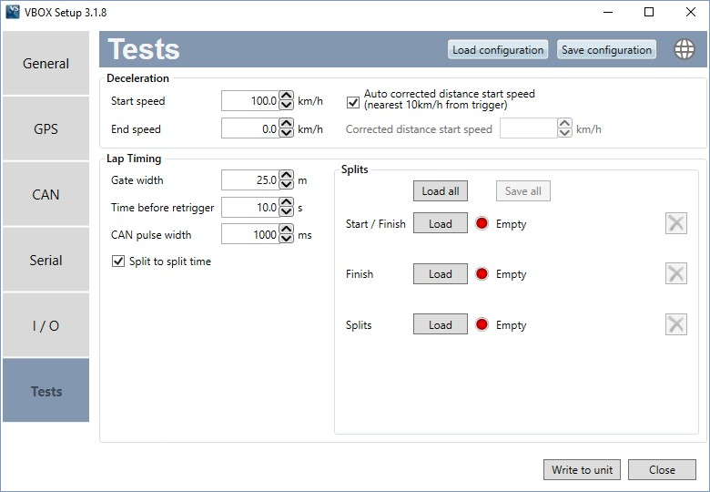
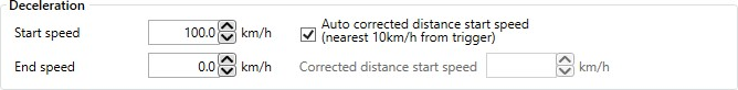
| Deceleration | Here you can configure the start and end speed for non-trigger deceleration tests. Auto Corrected Distance Start Speed – This sets the Speed Sensor to use the nearest rounded 10 km/h speed when the trigger is activated. For example, if the trigger speed was 104 km/h then 100 km/h would be the nominated start speed for the corrected brake stop distance. Corrected Distance Start Speed – If you do not select the auto option, you can specify a speed value you want to correct all deceleration tests to. |
 |
| Lap Timing |
Gate Width – This configures the width of any gates set in the software. This is a useful feature when two parts of a track run very close to each other, or the pit lane is next to the start/finish line, as lowering this value can stop the virtual line from being triggered at the incorrect area of the circuit. |
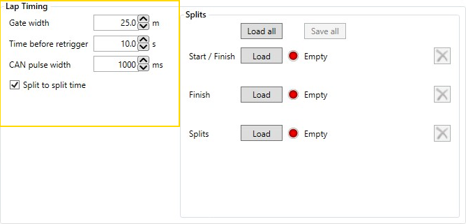 |
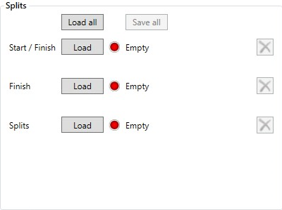
| Splits |
Use the ‘Load all’ button to load an .SPL or a .DSF file containing start/finish and split gates. Optionally, you can load split points, finish line or Start/Finish line separately, by using the ‘Load’ buttons next to each split type. Files loaded via these buttons will only use the selected information from them –i.e. a file containing a start/finish gate and 6 splits will only load the start/finish gate when loaded via the Start/Finish ‘Load’ button. |
 |