DGNSS / RTK Modes - VBOX 3iS
For more information on what DGNSS is and how it works, click here. For more information on RTK, click here.
VBOX 3iS supports an RTK connection using NTRIP. For more information on how this is set up, click here.
How to enable DGNSS Modes
VBOX 3iS must have the correct DGNSS mode enabled via the VBOX Setup Software, the Front Panel of the unit or using the VBOX Manager before it is capable of receiving and using the DGNSS correction information transmitted by a Local Base Station or NTRIP service.
Available modes:
- SBAS - SBAS differential corrections are received from the nearest Geo-stationary SBAS satellite.
- RTCM - RTCM corrections are received by the VB3i via a Racelogic telemetry module and a locally placed Base station. Contact Racelogic or your local agent for more details.
- CMR - 2 cm correction (Trimble standard message type).
Only selectable with VBOX 3iSR RTK variant. - RTCM v3 - 2 cm correction (RTCM standard message type).
Only selectable with VBOX 3iSR RTK variant. - MB Rover - Mode for use in Moving Base ADAS applications.
Only selectable with VBOX 3iSR RTK variant. - MB Base - Mode for use in Moving Base ADAS applications.
Only selectable with VBOX 3iSR RTK variant. - NTRIP - Internet-based subscription service, more information on this can be found here.
Only selectable with VBOX 3iSR RTK variant.
VBOX Setup
- Ensure VBOX 3iS is powered.
- Connect VBOX 3iS to a computer using the supplied loom, and connect the serial plug labelled 'Config' to the computer's serial port, this can be done via a serial > USB converter if required.
- Open VBOX Setup and connect to VBOX 3iS by selecting the correct COM Port.
- Select the 'GNSS' menu and then the 'Settings' tab.
- Choose the desired DGPS Mode and RS232 baud rate settings from the 'DGPS' options.

- Select 'Write to unit' to save the settings.
Front Panel
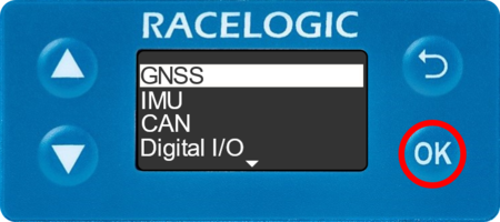
- Press the 'OK' button to enter the menu, navigate to 'GNSS' and press the 'OK' button.
 |
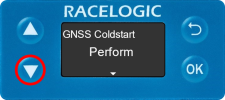
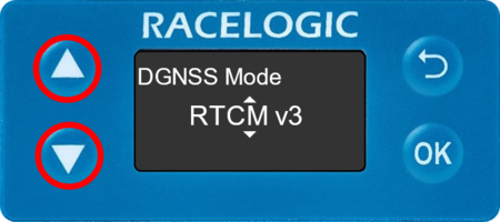
- Navigate to 'DGNSS Mode' using the 'Up' and 'Down' arrows. It will display whichever mode has been previously set.
 |
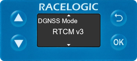 |
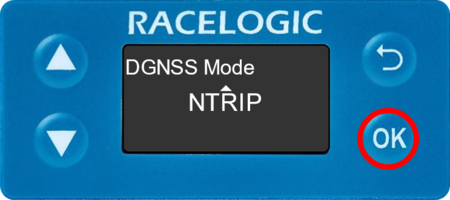
- If you would like to change the setting, press the 'OK' button then select the desired option using the 'Up' and 'Down' arrows.
 |
 |
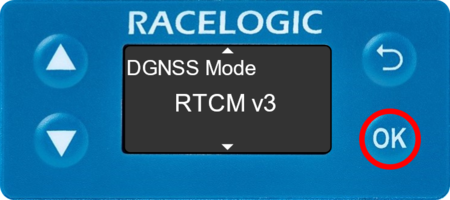
- Press the 'OK' button again to confirm.
 |
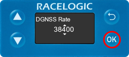
- Navigate to 'DGNSS Rate' using the 'Up' and 'Down' arrows. It will display whichever mode has been previously set.
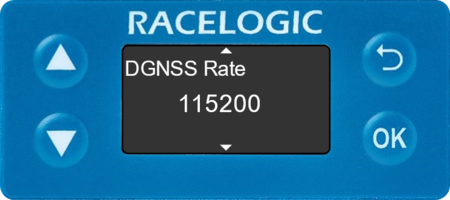 |
- If you would like to change the setting, press the 'OK' button then select the desired option using the 'Up' and 'Down' arrows.
 |
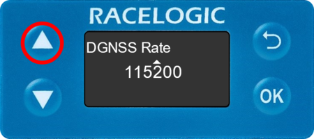 |
- Press the 'OK' button again to confirm.
 |
Using with Local DGNSS Base Station
When VBOX 3iS is used in conjunction with a local DGNSS Base Station, the positional accuracy can be improved from the standard 3 m 95 % CEP.
There are two available Base Station options:
40 cm positional accuracy:
If VBOX 3iS/VBOX 3iSR is used with an RTCM-V2 enabled Base Station, then the positional accuracy is increased to 40 cm 95 % CEP. The height accuracy is improved to 1 m 95 % CEP.
2 cm positional accuracy:
If VBOX 3iSR is used with an RLVBBS4RG or RLVBBS5 Base Station, then the positional accuracy is increased to 2 cm.
- CMR 2 cm correction (Trimble standard message type).
- RTCMv3 2 cm correction (RTCM standard message type) RECOMMENDED.
RTCMv3 is recommended as the default RTK 2 cm correction type. This message format is a globally recognised type and more resilient to data loss caused by radio errors.
Solution type lookup table
| Solution Type | Definition |
|---|---|
| 0 | None |
| 1 | GNSS only |
| 2 | GNSS DGNSS (inc RTCMv2 40 cm) |
| 3 | RTK Float |
| 4 | RTK Fixed |
| 5 | Fixed position |
| 6 | IMU Coast (Kalman Filter) |
0 = None
GNSS receiver cannot compute a solution for a position.
1 = GNSS only
Position computed from GNSS only.
2 = GNSS DGNSS
Position computed from assisted GNSS, this includes SBAS and Base Station DGNSS corrections.
3 = RTK Float
Position computed from GNSS corrected by RTK. Float means the GNSS receiver is still calculating the integer ambiguity, a small error will be present on the position computation at this time.
4 = RTK Fixed
Position computed from GNSS corrected by RTK. Fixed means the integer ambiguity is established and the optimum position correction is applied resulting in sub 2 cm relative accuracy in good conditions. The maximum period of time that the unit will remain in an RTK fixed state after it last received a valid RTK correction message is 15 seconds. After this time, the unit will revert to an RTK Float status.
5 = Fixed position
GNSS receiver position is fixed/locked. This is primarily used for base station receivers.
6 = IMU Coast
Position computed from the Kalman filter when GNSS is lost, inertial data from the IMU is used to maintain a solution for position until the GNSS is re-established. This solution type can be maintained for a maximum time of 600 seconds (10 minutes) when using Wheel Speeds, or 120 seconds (2 minutes) without wheel speeds, after which the solution type will change to 0.