03 Front Panel - VBOX 3iS Single Antenna RTK (v1)
Overview
|
To facilitate unit configuration, VBOX 3iS has an OLED display and four membrane buttons on the front panel. Alternatively, you can use VBOX Manager to configure the VBOX 3iS unit. VBOX Manager will mirror the functionality of the front panel on the VBOX 3iS. |
 |
Buttons
| Menu up / Increase the value when editing a number. |  |
Move to the previous menu level. | |
| Menu down / Decrease the value when editing a number. |
|
Enter the menu / select menu item for adjustment. |

Display
Startup
| When the VBOX 3iS is powered up, it will display the RACELOGIC logo along with the serial number of the unit. Next, it will change to display the firmware version of the unit. |  |
|
When the unit has initialised and any warnings have been cleared, the number of satellites will be displayed along with the accuracy. |
 |
|
Press the 'Down' arrow to open the status screen where you can view information about Speed, Satellite count, RTK Status and Wheel Speed. Press the 'Up' arrow to return to the main screen. |
 |
Settings Menu
You can access the menu by pressing the 'OK' button. Use the 'Up' and 'Down' arrows to navigate through the menu and press the 'OK' button to enter a submenu.
GNSS
| You can use this menu to configure the GNSS settings. |  |
GNSS Coldstart |
This setting will perform a coldstart of the GNSS Engine. You can find more information here. |
Dynamic Mode |
This setting lets you change the sensitivity of the GNSS engine. |
High (default) |
For high dynamic applications such as brake stop testing. |
Medium |
Suitable for all other testings. |
Low |
For less dynamic applications, such as steady state speed measurement or coast-down testing. |
DGNSS ModeAvailable modes are:
|
Sets the DGNSS mode. |
DGNSS Rate
|
This setting configures the DGNSS baud rate. To make sure that VBOX 3iS receives the DGNSS correction signal, you must set the correct DGNSS rate. All Racelogic blue boxed radios use 115200 kbit/s, and Satel grey boxed radios use either 19200 kbit/s or 38400 kbit/s. Note: Increasing this value will reduce the number of satellites the VBOX will be able to use. |
Elevation mask10 (default), 15, 20, 25 |
This setting lets you change the elevation mask, which is selectable from 10 to 25°. f the testing area has nearby trees or buildings, you may benefit from increasing this value to reduce the effect of multipath. You can find more information here. |
IMU
| This menu can be used to configure the internal/external IMU settings. |  |
IMU Integration |
This setting enables IMU integration. This action will add IMU channels to CAN ID 31B and 31C. |
IMU Location |
This setting specifies whether the speed sensor will be using its in-built IMU or an external IMU. Note: This option is only presented when the IMU integration is 'Enabled'. |
Roof Mount |
This setting specifies whether you are using a roof-mounted IMU from Racelogic or not. When it is 'Enabled', it will automatically add a 1 m z-offset, translating the filtered speed down into the vehicle towards the centre of gravity. The 'Ant to IMU Offset' will become 'Ant to Ref. Offset'. Note: This option is only presented when the IMU Location is set to ‘External’. |
Wheel Speed InputIMPORTANT |
This setting allows wheel speeds to be passed into the Kalman Filter. If the unit cannot detect CAN data, you will see a Warning Message on the front panel. Note: This option is only presented when the IMU integration is 'Enabled'. This action will add the Wheel Speeds channel to CAN ID 31D. |
Ant to Wheel Offset |
This setting specifies the x,y, and z distances between the antenna and the wheel speed reference point. The reference point is the centre point between the rear wheels. You can find more information here. Note: This option is only presented when Wheel Speed Input is 'Enabled'. |
Ant to IMU/Ref. Offset |
When Roof Mount is 'Disabled' - Provides the x,y, and z offset values from the antenna to the Speed Sensor/IMU that is required for the Kalman Filter algorithm. When Roof Mount is 'Enabled' - Becomes 'Ant to Ref. Offset' and provides the x,y, and z offset values from the roof-mounted IMU to the nominated reference point where all measurements will be made. |
Side facing down |
Select the orientation of the VBOX 3iS side facing down. This is only applied once the IMU menu is exited to the Main Menu. When the orientation is changed, the Kalman Filter is reset. Note:
|
Side facing forward |
Select the orientation of the VBOX 3iS side facing forward. This is only applied once the IMU menu is exited to the Main Menu. When the orientation is changed, the Kalman Filter is reset. Notes:
|
Pitch/Roll Offset |
Auto Level - Begins the process of levelling the IMU calculated Pitch and Roll Angles. Once selected, the unit averages the pitch/roll angles over a 5-second period and will then subtract/add the averaged values to make the pitch/roll angle 0. This offset will be displayed on the main screen. Clear - Clears the current pitch/roll offset values. |
Gyro Offset |
Auto Level - Begins the process of levelling the IMU calculated Pitch, Roll and Yaw Rates. Once selected, the unit averages the rates over a 5-second period and will then subtract/add the averaged values to make the rates equal to 0. These offsets will be displayed on the main screen. If the IMU location is set to External and the unit cannot detect an external IMU, it will display an error message. Clear - Clears the current offset values.
|
CAN
| You can use this menu to configure the CAN settings. | 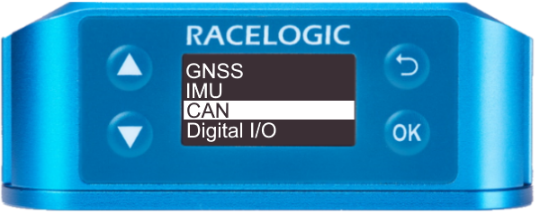 |
CAN Baud Rate125 kbit/s, 250 kbit/s, 500 kbit/s (default), and 1 Mbit/s |
In this setting you can select the CAN baud rate at which the data will be transmitted from the unit. |
CAN Termination |
Enables or disables the CAN Termination. |
Output Rate1 Hz, 5 Hz, 10 Hz, 20 Hz, 50 Hz, and 100 Hz (default) |
Determines the rate at which data is sent out via CAN. |
Digital I/O
| This menu can be used to configure the digital input/output settings. |  |
Digital Input |
Defines what the digital input will be used for, either a brake trigger or as a lap pulse. |
Brake Trigger |
Used to start brake trigger tests. |
Track Marker |
Enabling this mode allows the Digital Input to be used as a lap pulse. The input switch can be used to set a start/ finish line, set a separate finish line, set a split line, clear all virtual lines, and perform a coldstart. |
|
Set a start-finish line |
Press and release the input switch. GNSS speed must be greater than 5 km/h and the virtual line will be perpendicular to the direction of travel. |
|
Set a separate finish line |
Press and hold the input switch for more than 5 seconds. GNSS speed must be greater than 5 km/h and the virtual line will be perpendicular to the direction of travel. |
|
Set a split line |
Double-press the input switch. For this to register, the GNSS speed must be greater than 5 km/h and the virtual line will be perpendicular to the direction of travel. |
|
Clear all virtual lines |
Short press followed by a long press (more than 1.5 s). |
|
Perform a coldstart |
Ground the input at the same time as connecting VBOX 3iS to power. |
Digital Output |
Defines the digital output of the Speed Sensor. |
Speed |
Sends a configured number of pulses per m. |
Lap Pulse |
Sends a pulse every time the start/finish line is crossed. |
Tests
| This menu can be used to configure brake test/lap timing settings. |  |
Brake test speed |
Start Speed - Defines the start speed at which the test will begin (100 km/h by default). End Speed - Defines the end speed at which the test will end (0 km/h by default). |
Corrected Dist. |
Auto corrected - This sets the speed sensor to use the nearest rounded 10 km/h speed when the trigger is activated. For example, if the trigger speed was 104 km/h, then 100 km/h would be the nominated start speed for the corrected brake stop distance. Value - 85 km/h by default. |
S/F Gate Width |
Defines the width of any gates set (25 m by default). |
Retrigger Time |
Defines the minimum amount of time needed between triggers for the second trigger to be valid. If a trigger is detected before this time, it will be ignored (1 s by default). |
Lap Pulse Width |
Defines the width of the pulse emitted when crossing a lap or split timeline (1 s by default). |
Split to Split time |
Determines whether the 'Split Time' CAN channel is either the total lap time at the split cross or the delta time between split lines. SF - Split or Split - Split |
ADAS
|
This menu can be used to configure the ADAS settings. |
|
ADAS Mode |
|
|
Off (default) |
ADAS mode is disabled |
|
1 Target |
Configures VBOX 3iS for 1-target mode |
|
2 Target |
Configures VBOX 3iS for 2-target mode |
|
3 Target |
Configures VBOX 3iS for 3-target mode |
ADAS Function |
Note: This option is only presented when 2 Target or 3 Target ADAS mode is selected. |
|
Target 1 |
Configures VBOX 3iS as 'Target Vehicle 1'. |
|
Target 2 |
Configures VBOX 3iS as 'Target Vehicle 2'. |
|
Target 3 |
(Only presented when 3 Target ADAS mode is selected) Configures VBOX 3iS as 'Target Vehicle 3'. |

Robot Mode
|
Sets VBOX 3iS up for connection to a Robot. You can find more information here. |
 |
Off (default) |
|
ABD Path Follow |
Select this menu option to set the VBOX into Path Follow ABD mode, for use in Robot vehicle testing. |
ABD Open Loop |
Select this menu option to set the VBOX into Open Loop ABD mode, for use in Robot vehicle testing. |
ABD Pedestrian |
Select this option to configure the VBOX for use with an ABD Pedestrian robot. |
DSD UFO |
Select this menu option to set the VBOX into UFO DSD mode, for use in Robot vehicle testing. |
DSD Vehicle |
Select this menu option to set the VBOX into Vehicle DSD mode, for use in Robot vehicle testing. |
VEHICO |
Select this menu option to set the VBOX into Vehicle mode, for use in Vehicle robot systems. |
Enable |
Auto Configure - Automatically configure VBOX 3iS to work with the Vehicle system by applying settings. Set Datum Point - Selecting will use the current location of the GNSS antenna as the Datum point, the origin point of the local X-Y coordinate system, from which all positional information will reference. Track Direction – Set Track Ref - The track direction dictates the direction in which the Vehicle system will consider its ‘North’ value. VBOX 3iS will automatically work out the heading and apply this heading as the track direction. Enter Heading - Alternatively to setting the 'Track Direction', a numerical heading value can be manually entered. Clear - Selecting this option will clear the current track direction before setting the current antenna location as the datum point. |
Disable |
Disable the VEHICO mode. |
Warnings
If GNSS, IMU operation or Wheel Speeds (No Data) have an error, the screen will flash a descriptive warning (flashing warning triangle + text describing the error).
Kalman Filter
If you have enabled IMU Integration, the main screen should show an indication of the Kalman Filter status.
- Once the unit has acquired satellite lock, the display will read Filter Initialising - Remain Stationary for 30s.
- The message will count down to 0 seconds and change to Stationary Initialisation Complete
- After 2 seconds, it will display Waiting For Movement.
Note: If the speed rises above 0.8 km/h at any stage during the steps above, the countdown and filter initialisation will reset and the following message will be displayed: Speed>0.8kph – Initialisation reset.
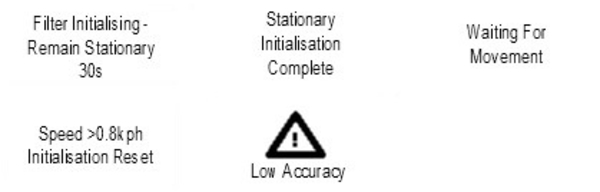
When the unit has detected the speed, the display will show an indication of the Kalman Filter quality in relation to the Speed Quality Channel output on CAN ID 0x306. The display will read either:
- Low Accuracy when the speed quality is >0.1 km/h.
- Medium Accuracy When the speed quality is <0.1 km/h.
- OK When the speed quality is <0.06 km/h for at least 5 seconds.
Factory Reset
If the unit has become unresponsive or you would like to reset the unit to its factory settings, you can do this by pressing the Up and Down arrow buttons simultaneously and holding them for 5 seconds. After this period, the screen will go blank and reboot to the start-up screen.

Note: Receiver settings (Dynamic Mode, DGNSS Mode, DGNSS Rate and Elevation mask) will not reset.