Front Panel – VBOX 3i ADAS
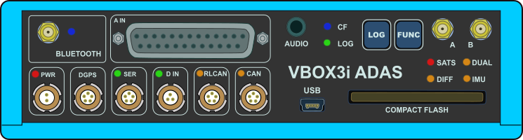 |
ConnectorsYou can find more information about the different inputs and outputs here. |
| BLUETOOTH | VBOX 3i ADAS comes equipped with a Bluetooth radio allowing configuration of the VBOX unit remotely along with remote output of real-time VBOX serial data, at the full 100 Hz data rate, to any Bluetooth capable PC or data logger. |
| A IN |
This is the analogue input connector. Each of the four analogue input channels on VBOX 3i ADAS has a dedicated analogue converter. Data is recorded from each channel simultaneously to avoid latency between analogue channel data. The analogue input connector also provides two power outputs that may be used for driving sensors. |
| PWR | This is the power connector. VBOX 3i ADAS can accept a supply voltage between 7 and 30 V DC. Low current consumption results in extended battery life. |
| DGPS | The RS232 port named DGPS is designated for connection to a DGPS radio, allowing the reception of Differential GPS (DGPS) data for local correction. |
| SER |
The primary RS232 port is used for all communication between the VBOX 3i ADAS unit and a laptop PC. The primary port is marked SER on the front panel of the VBOX 3i ADAS. In ADAS mode you can use this port with an ADAS radio. |
| D IN |
The ‘D IN’ connector contains the two digital inputs for the VBOX 3i ADAS.
|
| RLCAN | This connector is termination-enabled and is to be used with Racelogic modules and devices. |
| CAN |
The CAN port is used for Racelogic CAN output and for logging third-party CAN data to the .vbb file. |
| AUDIO | VBOX 3i ADAS can record audio tags synched with a set GNSS timestamp, with an accuracy of 0.5 seconds. |
| USB |
VBOX 3i ADAS includes a USB 2.0 connection that you can use to configure your VBOX unit and output real-time serial data at the full 100 Hz data rate. |
| ANTENNA A | The primary antenna connector. |
| ANTENNA B | The secondary antenna connector. |
LEDs
| CF | Indicates that the unit is writing to the Compact Flash card. |
| LOG | Indicates that the unit is capturing data to the CF card and the current logging rate. |
| SATS | Indicates the number of satellites being tracked. |
| DUAL | Indicates whether dual antenna mode is enabled/disabled and that antenna lock is fixed. |
| DIFF | Indicates the DGPS status. |
| IMU | Indicates the IMU integration and initialisation status. |
| BLUETOOTH | Indicates that communication has been initialised and that Bluetooth connection has been confirmed. |
| PWR | Indicates whether the unit is powered and ready to use or not. |
| SER | Indicates incoming serial traffic and that data has been decoded and is being logged. |
| D IN | Indicates activated/triggered event marker input. |
| RLCAN | Indicates that expected incoming CAN data has been decoded properly and is being logged. |
| CAN | Indicates that expected incoming CAN data has been decoded properly and is being logged. |
| You can find the full description of the different behaviours of the LEDs here. | |