ADAS Testing Installation and Configuration - VBOX 3i RTK
|
This page contains a detailed installation and configuration guide for a basic ADAS testing setup. These are step-by-step instructions that you should complete to get your ADAS testing systems ready. This page is for ADAS testing with VBOX 3i RTK. |
Step 1: Inventory
|
The first step includes deciding what equipment you need for the test scenario you will be working with, and checking that you have the modules and accessories you need before you start the installation on and in your vehicle(s). We suggest that you:
Note: You will need a Laptop with the VBOX Setup software installed to configure all the vehicles. Check that you have the latest software and firmware versions installed. You can find the latest versions available here. (If you are installing VBOX software for the first time, the VBOX Test Suite installer will include VBOX Setup as well.) Click on the equipment headings below to see relevant lists of equipment for that setup. |
- ►Equipment for the Subject Vehicle
-
Required
- VBOX unit - VBOX 3i RTK
- Power cable (vehicle to VBOX - RLCAB010LE)
- Laptop with VBOX Setup software installed
- USB cable (VBOX to Laptop - RLCAB066-2)
- Primary GNSS Antenna (ACS324)
- Secondary GNSS Antenna (ACS156RTK)
- 2 x GNSS antenna cables (RLCAB080-4)
- ADAS Server radio* (RTMXB2)
- ADAS radio antenna* (RLACS218)
- ADAS radio cable* (radio to VBOX - RLCAB005)
- DGPS/RTK device
- DGPS/RTK device cables
Optional
- IMU (VBIMU04/VBIMU05/VBIMU05-S)
- IMU cable (IMU to VBOX - RLCAB119L)
- Battery (VBOX power supply - RLACS333-L)
- Other Racelogic Modules and their corresponding cables
- VBOX Manager (RLVBFMAN)
- VBOX Manager cable (RLCAB005C)
- Video VBOX
*These are not required in scenarios where you are not using target vehicles (Remote VBOX Targets).
_750px.png?revision=1)
- ►Equipment for the Target Vehicle
-
Required
- VBOX unit - VBOX 3i RTK
- Power cable (vehicle to VBOX - RLCAB010LE)
- Primary GNSS Antenna (ACS324)
- Secondary GNSS Antenna (ACS156RTK)
- 2 x GNSS antenna cables (RLCAB080-4)
- ADAS client radio (RTMXB2)
- ADAS radio antenna (RLACS218)
- ADAS radio cable (radio to VBOX - RLCAB005)
- DGPS/RTK device
- DGPS/RTK device cables
Optional
- IMU (VBIMU04/VBIMU05/VBIMU05-S)
- IMU cable (IMU to VBOX - RLCAB119L)
- Additional Laptop with VBOX Test Suite and VBOX Setup software installed.
- Battery (VBOX power supply - RLACS333-L)
- MFD Touch (RLVBMFDT)
- VBOX Manager (RLVBFMAN)
- VBOX Manager cable (RLCAB005C)
_750px.png?revision=1)
- ►Surveying Equipment
-
If you need to survey any points or lines when configuring your vehicles and the test, you will need to use survey equipment. Choose the equipment based on the configurations you need:
- Survey antenna (RLACS320)
- Survey antenna cable (RLCAB067)
- Survey Pole (RLACS168)
Used to survey vehicle shapes, static targets and points on a straight line. - Survey Trolley and Backpack (RLACS173)
Used to survey curved and complex lines. - Battery (VBOX power supply - RLACS333-L)
Used to power the VBOX unit so that you can move around when surveying.
Step 2: Install the Hardware on your Test Vehicles
These are the steps for mounting and connecting the relevant equipment on and in your test vehicles.
Click on the blue headings below to see the relevant steps for each setup.
- ►Install and Connect all Target Vehicle Hardware
-
If you are using Remote VBOX Targets (target vehicles):
- Go to the vehicle you want to use as a target.
- Unpack the equipment you want to use on that vehicle.
- Connect one end of an antenna cable to the connector on the primary GNSS antenna.
- Connect one end of a second antenna cable to the connector on the secondary GNSS antenna.
- Place the GNSS antennas on the roof of the vehicle.
Note:
- In dual antenna mode, the antennas should be positioned so that their gold antenna connectors are pointing in the same direction.
- When using dual antennas, the antenna separation affects the accuracy of the dual antenna-derived data channels. You will experience the greatest accuracy if they are mounted with a separation of between 0.5 m to 2.5 m. You can read more about antenna separation and accuracies here.
You can find more information about antenna placement and equipment for antenna placement here.- Connect the primary GNSS antenna to antenna port A on the target's VBOX unit.
- Connect the secondary antenna to antenna port B on the target's VBOX unit.
- Connect the ADAS radio antenna to the ADAS radio unit.
- Place the ADAS radio antenna on the roof of the vehicle.
Note: The ADAS radio antenna must be at least 50 cm away from any other radio antenna.
- Connect the ADAS radio unit to the SER port on the target's VBOX unit with the RLCAB005.
- Connect the RTK device you are using to the CAN port on the target's VBOX unit.
- If you need information about setting up and using a Base Station for RTK correction, click here.
- If you need information about setting up and using an NTRIP Modem for RTK correction, click here.
- Connect any additional Racelogic modules that you want to use, such as an IMU for Kalman Filter.
You can find information about how to install and connect the different modules here.
- Connect the power cable to the PWR port on the target's VBOX unit.
- Use the USB cable (RLCAB066-2) to connect the Laptop with VBOX Setup installed to the USB port on the target's VBOX unit.
- Open VBOX Setup.
- Select the relevant COM port and click Connect.
- Select the DGPS/RTK mode:
Open the GPS menu.
Select the mode and set the baud rate you are using:
RTCM v3 (Static base) - the same baud rate as your client radio
NTRIP - 115200 kbit/s
MB-Rover - 115200 kbit/s
MB-Base - 115200 kbit/s - Open the Dual Antenna menu.
- Toggle the Enable dual antenna mode switch.
- Measure and enter the antenna separation value.
- Select the antenna orientation, Pitch mode or Roll mode.
- Open the ADAS menu.
- Set the Mode to Target.
- Set the total number of targets you are using and the number of the target you are setting up.
- Click Write to unit.

At this point, you have completed the hardware installation on your target vehicle.
Note:
- If you need to survey vehicle points for the target vehicle shape as part of the test configuration, you must use your Subject VBOX unit (set up as described below) to do this and the target vehicle that is being surveyed must be in a location with a clear view of the sky and access to RTK corrections.
- ►Install Relevant Subject Vehicle Hardware
-
- Go to the Subject Vehicle.
- Unpack the equipment you want to use on that vehicle.
- Connect one end of an antenna cable to the connector on the primary GNSS antenna.
- Connect one end of a second antenna cable to the connector on the secondary GNSS antenna.
- Place the GNSS antennas on the roof of the vehicle.
Notes:
- In dual antenna mode, the antennas should be positioned so that their gold antenna connectors are pointing in the same direction.You can find more information about antenna placement and various equipment for antenna placement here.
- When using dual antennas, the antenna separation affects the accuracy of the dual antenna-derived data channels. You will experience the greatest accuracy if they are mounted with a separation of between 0.5 m to 2.5 m. You can read more about Antenna Separation and accuracies here.
- Connect the ADAS radio antenna to the ADAS radio unit.
- Place the ADAS radio antenna on the car roof.
Note: The radio antenna must be at least 50 cm away from any other radio antenna.
- Prepare any additional Racelogic modules that you want to use, such as an IMU for Kalman Filter.
You can find information about how to install and connect to VBOX 3i RTK for the different modules here.
- Do not make any connections to your subject's VBOX unit yet.
At this point, your Subject Vehicle is ready to be configured.
Notes:
- If you need to survey vehicle points for the subject vehicle shape as part of the test configuration, your vehicle must be in a location with a clear view of the sky and access to RTK corrections.
- You will be using the subject's VBOX unit to configure all elements of the ADAS test.
Step 3: Configure ADAS Objects
|
If you are surveying vehicle points, reference heading, static targets, sign posts or lines, you can now prepare your surveying equipment:
Note: When you see the Save icon in survey and configuration windows, you can save your current configuration to a file on your computer. You can then load these files into VBOX Setup during future configurations. |
Subject Vehicle Shape
|
Click the Edit button to the right of Subject Vehicle to configure its vehicle points and line reference points.
You can now decide how you want to configure the subject vehicle shape. |
- ►Load From File
-
Load an already configured vehicle shape from a saved file.
- Click on the Load from file button.
- Navigate to the file you wish to use.
- Click Load.
When the file has been loaded, you will see an overview of the configured vehicle points and line reference points from that file.
The preview window will show you your points.
- Vehicle points are blue and numbered.
- Line reference points are yellow and lettered.
This is a great way to quickly confirm that your vehicle shape is looking as expected and that your line reference points are where you want them.
You can edit points by changing the values in the X and Y boxes for each point.
You can delete a point by clicking on the bin icon to the right of the point.
- Click OK when you are happy with all your vehicle and line reference points.
IMPORTANT
You must add at least one ADAS object when configuring in Subject Mode. If you do not add an ADAS object, the Subject mode will be set to Disabled when you click Write to unit.
- ►Survey From Live Position
-
Use a survey pole to set the vehicle points that configures the shape of the test vehicle(s).
- Click Survey from live position.
The Survey: Subject Vehicle Shape window will open.

Set the origin and forward direction.
- Place the survey antenna on the vehicle roof where you want your origin point to be.
The origin should be at the same location as your primary antenna.
- Click Set origin.
- Move the survey antenna forward on the roof.
The forward direction used in the configuration will be drawn from the origin point to your forward direction point. This should be along the centre of the vehicle and towards the front of the vehicle.
- Click Set forward direction.
You will now see the window change to display an overview of configured points on the left side of the window as well as the preview diagram on the right side of the window.
- Mount the survey antenna on a survey pole.
- Place the survey pole next to the vehicle at a location that you wish to use as a vehicle point.
- Click on the Add vehicle point button to record the first vehicle point.
- Set the next point by moving the survey pole with the survey antenna to another point you wish to use.
- Click the Add vehicle point button.
- Repeat the process until you have set the required points (max 24).
You can also add up to 3 Line reference points in this window.
- Use the survey pole and survey antenna to set the location of the points.
- Click the Add line ref. point button to record them.
The preview window will show you your points as you add them.
- Vehicle points are blue and numbered.
- Line reference points are yellow and lettered.
This is a great way to quickly confirm that your vehicle shape is looking as expected and that your line reference points are where you want them.
You can edit added points by changing the values in the X and Y boxes for each point.
You can delete a point by clicking on the bin icon to the right of the point.
- Click OK when you have added all your vehicle and line reference points.
Your subject vehicle shape has now been configured.
IMPORTANT
You must add at least one ADAS object when configuring in Subject Mode. If you do not add an ADAS object, the Subject mode will be set to Disabled when you click Write to unit.
- ►Edit points
-
Set points without using surveying equipment by manually entering offsets from the antenna.
You can set up to 24 vehicle points.
- Click on the Add vehicle point button to add a point to your vehicle shape.
- Add the X-axis distance (m) based on the antenna offset.
- Add the Y-axis distance (m) based on the antenna offset.
Note: Positive values are in front of, or to the right of, the antenna. Negative values are behind, or to the left of, the antenna.
You can also set up to 3 Line reference points to your vehicle in this survey window.
- Click on the Add line ref. point button to add a line reference point to the Subject Vehicle.
- Measure from the primary GNSS antenna to the location you wish to use as the Line reference point.
- Add the X-axis distance (m) based on the GNSS antenna offset.
- Add the Y-axis distance (m) based on the GNSS antenna offset.
The preview window will show you your points as you add them.
- Vehicle points are blue and numbered.
- Line reference points are yellow and lettered.
This is a great way to quickly confirm that your vehicle shape is looking as expected and that you line reference points are where you want them.
You can edit added points by changing the values in the X and Y boxes for each point.
You can delete a point by clicking on the bin icon to the right of the point.
- Click OK when you have added all your vehicle and line reference points.
Your subject vehicle shape has now been configured.
IMPORTANT
You must add at least one ADAS object when in configuring in Subject Mode. If you do not add an ADAS object, the Subject mode will be set to Disabled when you click Write to unit.
Target Vehicle Shape
|
Now it is time to configure the vehicle points for your target vehicle(s). You can have a maximum of 3 remote targets. Note: You will still be using the subject's VBOX unit and its connected modules and laptop for this step.
You can now decide how you want to configure the target vehicle shape. |
- ►Load From File
-
Load an already configured vehicle shape from a saved file.
- Click on the Load from file button.
- Navigate to the file you wish to use.
- Click Load.
When the file has been loaded, you will see an overview of the configured vehicle points and the line reference point from that file.
The preview window will show you your points.
- Vehicle points are blue and numbered.
- Line reference points are yellow and lettered.
This is a great way to quickly confirm that your vehicle shape is looking as expected and that your line reference point is where you want it.
You can edit added points by changing the values in the X and Y boxes for each point.
You can delete a point by clicking on the bin icon to the right of the point.
- Click OK when you are happy with all your vehicle and line reference points.
Multiple Targets
If you want to use multiple targets, you need to repeat the target vehicle configuration above for each vehicle (Target Vehicle Hardware and Target Vehicle Shape)
- ►Survey From Live Position
-
Use a survey pole to set the vehicle points that configure the shape of the target vehicle(s).
- Click Survey from live position.
The Survey: Remote VBOX Target Shape window will open.
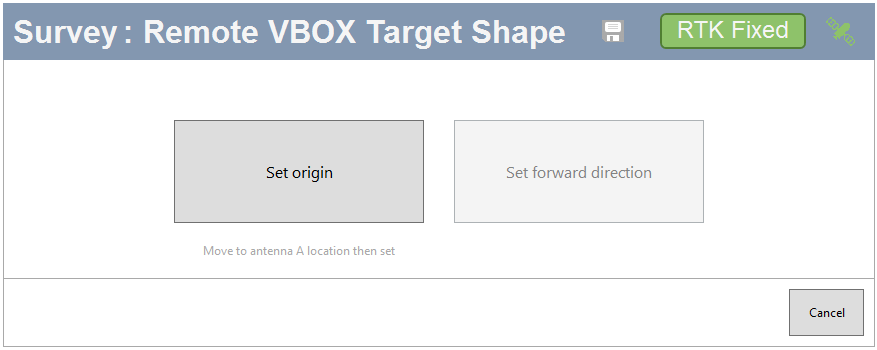
First, you must set the origin and the forward direction:
- Remove the survey antenna from the survey pole.
- Place the survey antenna on the vehicle roof where you want your origin point to be.
The origin should be at the same location as your primary antenna.
- Click Set origin.
- Move the survey antenna forward.
The forward direction used in the configuration will be drawn from the origin point to your forward direction point. This should be along the centre of the vehicle and towards the front of the vehicle.
- Click Set forward direction.
You will now see a new window display an overview of configured points on the left side of the window as well as the preview diagram on the right side of the window.
- Mount the survey antenna on the survey pole again.
- Place the survey pole next to the vehicle at a location that you wish to use as a vehicle point.
- Click on the Add vehicle point button to record the first vehicle point.
- Set the next point by moving the survey pole with the survey antenna to another location you wish to use.
- Click the Add vehicle point button.
- Repeat the process until you have set the required points (max 24).
You can also add 1 Line reference point in this window.
- Use the survey pole and survey antenna to set the location of the point.
- Click the Add line ref. point button to record it.
The preview window will show you your points as you add them.
- Vehicle points are blue and numbered.
- The Line reference point is yellow and lettered.
This is a great way to quickly confirm that your vehicle shape is looking as expected and that your line reference point is where you want it.
You can edit added points by changing the values in the X and Y boxes for each point.
You can delete a point by clicking on the bin icon to the right of the point.
- Click OK when you have added all your vehicle and line reference points.
- Click Write to unit to send the configuration to the connected VBOX unit.
Your target vehicle shape has now been configured.
Multiple Targets
If you want to use multiple targets, you need to repeat the target vehicle configuration above for each vehicle (Target Vehicle Hardware and Target Vehicle Shape)
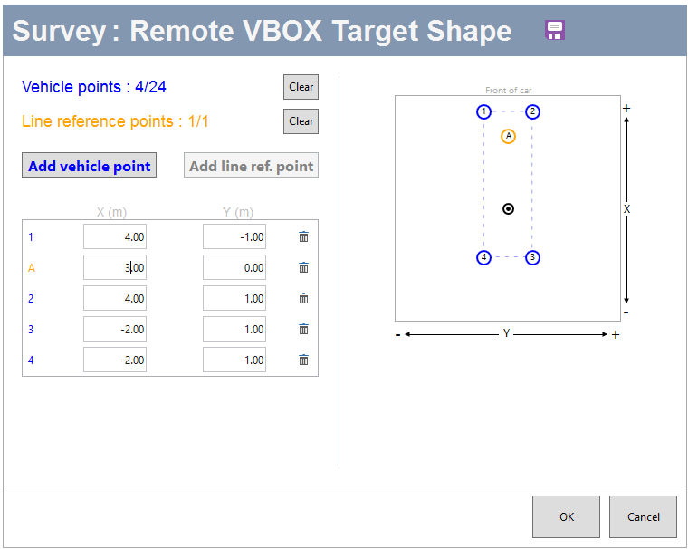
- ►Edit points
-
Set points, without using surveying equipment, by manually entering offsets from the antenna.
You can set up to 24 vehicle points.
- Click on the Add vehicle point button to add a point to your vehicle shape.
- Add the X-axis distance (m) based on the antenna offset.
- Add the Y-axis distance (m) based on the antenna offset.
Note: Positive values are in front of, or to the right of, the antenna and negative values are behind, or to the left of, the antenna.
You can also set 1 Line reference point to your vehicle in this survey window.
- Click on the Add line ref. point button to add a line reference point to the Subject Vehicle.
- Measure from the primary GNSS antenna to the location you wish to use as the Line reference point.
- Add the X-axis distance (m) based on the GNSS antenna offset.
- Add the Y-axis distance (m) based on the GNSS antenna offset.
The preview window will show you your points as you add them.
- Vehicle points are blue and numbered.
- Line reference points are yellow and lettered.
This is a great way to quickly confirm that your vehicle shape is looking as expected and that your line reference point is where you want it.
You can edit added points by changing the values in the X and Y boxes for each point.
You can delete a point by clicking on the bin icon to the right of the point.
- Click OK when you have added all your vehicle and line reference points.
Your target vehicle shape has now been configured.Multiple Targets
If you want to use multiple targets, you need to repeat the target vehicle configuration above for each vehicle (Target Vehicle Hardware and Target Vehicle Shape)
Reference Heading
|
A reference line is used to provide a very stable heading reference for the calculation of noise free LatRref-tg1 (or tg2, tg3) and LngRref-tg1 (or tg2, tg3) channels. These channels are the lateral and longitudinal ranges between the subject and target vehicles based on the set reference heading. Note: You will still be using the subject's VBOX unit and its connected modules and laptop for this step. |
|
 |
- ►Surveying Reference Heading
-
- Make sure you have RTK fix.
- Click on the Survey button.
The Surveying window will open.
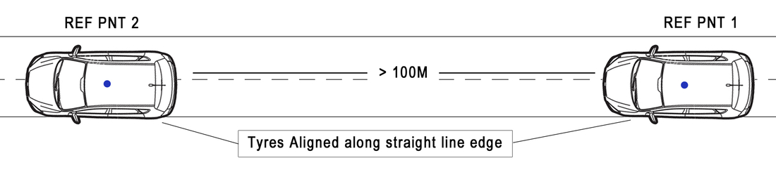
- Move the vehicle to the first nominated point along a straight line that runs perfectly parallel to the test track.
A good method for this is to get the front and rear tyres on one side of the vehicle perfectly aligned on a marked straight line. The vehicle should point in the direction you wish to set for the heading.
- Set the first point by clicking on the Set Point A button.
- Move the vehicle to a distance at least 100 m along the straight line. Make sure that the vehicle is re-aligned to the line.
- Click on the Set Point B button.
Note: The reference heading will be generated from the bearing of Point A to Point B.
- Click OK.


Note: If you have set the Reference heading, you can view it in the ADAS summary page.
You can find more information about the ADAS Parameter Definitions here.
Other ADAS Objects
You may need to use one or more other ADAS objects for reference in your test, such as static targets, lines and sign posts. If you do need one or more of these, click on the blue heading for the object you want to add to see the steps.
- ►Static Targets
-
If you want to add static targets you can follow the instructions below.
Note: You will still be using the subject's VBOX unit and its connected modules and laptop for this step.
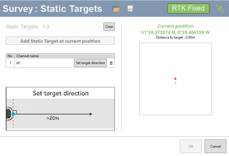
- Click Add Static Target.
The static target survey window will open.
You now have two options for adding static targets:
You can load existing static targets from a file (.VBC) You can Add static target at current position. Adding a Static Target at the current position:
- Click Add Static Target at current position to add a target point at the location of the survey antenna.
- Reverse the vehicle > 20 m (or move the antenna backwards from the target).
- Click set target direction.
You will see the target and direction shown in the preview window.
You can add up to 3 static targets.
Note: You can only have 5 targets in total, including both remote and static targets.
You can click Clear to delete added static targets.
You can click Save to save the added targets in a .VBC file.
- Click OK to finish.
- ►Lines
-
Lines are used to mark the edges of a road or a lane during the testing. You can have a maximum of 3 lines at any time. If the line you are surveying loops back on itself, for example, the centre line of a circular test track, you should add it as a Circuit Line.
Note: You will still be using the subject's VBOX unit to configure the lines.
Use the following steps if you need to set lines:
- Use the subject's VBOX unit.
-
Open the ADAS menu in VBOX Setup.
-
Select the type of line you wish to add: Road Line or Circuit Line
The Survey windows will open.
You now have two options, Load from File and Survey line.
Load From File
- Click on the Load from file button.
- Navigate to the file you wish to use.
- Click Load.
The file will be loaded into VBOX Setup and you can see the configured lines.
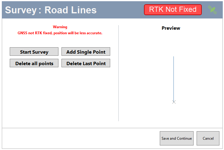
Survey Road Line
Click Survey Road Line.
There are 2 ways to survey a Road Line, performing a survey and adding single points.
Survey a Road Line
- Click Start Survey.
- Walk along the line you wish to use as a road line with the survey trolley.
The software will record the movement of the antenna you use for the survey and plot it as a line.
During the survey, you can see a preview of the line in the preview window.
- When you are happy with the surveyed line, click Save and continue.
This will open a preview window where you can see the surveyed line.
- Click on the OK button to save the line and the Cancel button to exit the survey and go back to the ADAS menu.
Add Single Point
You can add single points to create a road line.
- Move the survey antenna to the first point of your line and click on the Add single point button.
- Move your survey antenna to the next point on your line and click on the Add single point button.
- Repeat this step until you have completed your Road Line.
During the survey, you can see a preview of the line in the preview window.
- When you are happy with the surveyed line, click Save and continue.
This will open a preview window where you can see the surveyed line.
- Click on the OK button to save the line and the Cancel button to exit the survey and go back to the ADAS menu.
Notes:
- Road lines are always saved after a survey so that they can be used again via the Load from file option.
- If you need to make changes in the added points, you can delete the last added point or clear all added points and start again.
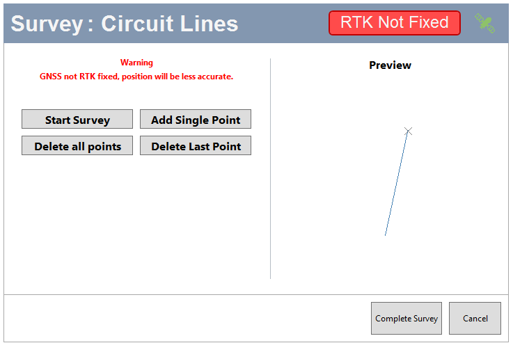
Survey Circuit Line
Click Survey Circuit Line.
There are 2 ways to survey a Circuit Line, performing a survey or adding single points.
Survey a Circuit Line
- Click Start Survey. Walk along the line you wish to use as a circuit line with the survey trolley.
- The software will record the movement of the antenna you use for the survey and plot it as a line.
During the survey, you can see a preview of the line in the preview window.
- When you are happy with the surveyed line, click Complete Survey.
This will open a preview window where you can see the surveyed line.
- Click on the OK button to save the line and the Cancel button to exit the survey and go back to the ADAS menu.
Add Single Point
You can add single points to create a circuit line.
- Move the survey antenna to the first point of your line and click on the Add single point button.
- Move your survey antenna to the next point on your line and click on the Add single point button again.
- Repeat this step until you have completed your circuit line.
During the survey, you can see a preview of the line in the preview window.
- When you are happy with the surveyed line, click Complete Survey.
This will open a preview window where you can see the surveyed line.
- Before you save the line, you can relocate the Entry Point (the red dot marks the entry point) on the track by clicking on the new location on the surveyed line. If you do not move the entry point, Setup will place it at the location of the first point of the line.
- Click OK to save the line and Cancel to go back to the ADAS menu without saving the line.
Notes:
- Lines are always saved after a survey so that they can be used again via the Load from file option.
- If you need to make changes to the added points, you can delete the last added point or clear all added points and start again.

- ►Sign Posts
-
By expanding the sign post section, you can enter data, such as:
- Sensor detection range
- Sensor detection angle
- Antenna to sensor offset
You can add up to 99 sign posts.
Note: You will still be using the subject's VBOX unit and its connected modules and laptop for this step.
- Click Add Sign Posts.
The Survey: Sign Posts window will open.
You can either add sign posts by using existing sign post files (.VBC files) or you can Add sign post at current position.
Add Sign Post at current position
- Move the survey antenna to the location of your sign post.
- Click on the Add Sign post at current position button.
- Repeat the process for each required sign post.
- When you have added the sign posts you need, click OK to continue.
You can see the sign posts in the preview window with the accompanying coordinates (lateral and longitudinal).
If you want to continue without using any added sign posts, click Cancel.
If you want to delete the added sign posts and start again, click Clear.
You can save the added sign posts to a .VBC file.
The sign posts will be visible on the map in the ADAS menu.


Step 4: Install and Connect all Subject Vehicle Hardware
| When you have finished configuring the ADAS objects, you can connect all the hardware on the Subject vehicle. |
|
|
Step 5: Send Configuration to Target(s)
|
If you have configured one or more target vehicles, and you wish to view the ADAS data on a connected display in your target vehicle(s), you will need to transfer the target vehicle configurations to the relevant target VBOX units.
Note: This process can take a couple of minutes. |
 |
Step 6: Final Checks
|
You should perform the following steps on all the vehicles in your test system before you start your test.
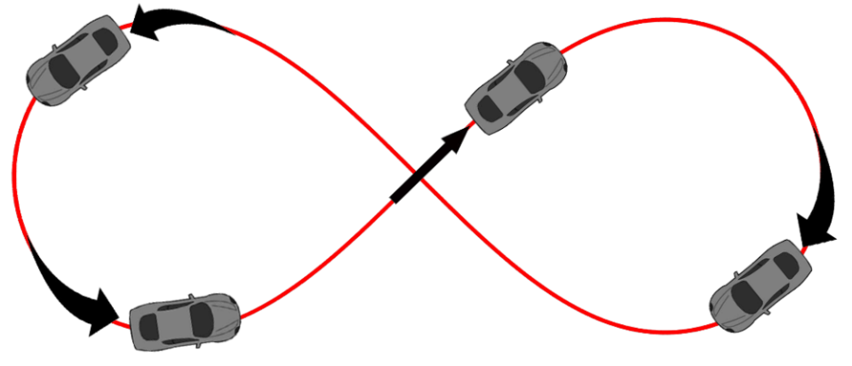
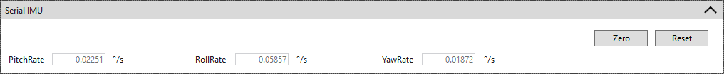
When using IMU integration, it requires an initialisation phase when the IMU is first connected to the VBOX after being configured. This will automatically run after the VBOX unit has successfully gained GPS and RTK.
|


Step 7: Start Testing
| Your ADAS configuration should now be complete and you can start your test. You will be able to see live previews of the configured ADAS ranges during your test. |