Quick ADAS Testing Installation and Configuration - VBOX 3i RTK
| This page contains a basic configuration guide for a typical setup for ADAS testing. These instructions outline the steps and their order to get your ADAS testing systems ready when using VBOX 3i RTK. |
Step 1: Inventory
|
The first step includes deciding what equipment you need for the test scenario you will be working with, and checking that you have the modules and accessories you need before you start the installation on and in your vehicle(s). We suggest that you:
|
|
|
_750px.png?revision=1) |
| Subject Vehicle Setup | Target Vehicle Setup |
- Surveying Equipment
-
If you need to survey any points or lines during the configuring your vehicles and the test, you will need to use survey equipment. Choose the equipment based on the configurations you need:
- Survey antenna (RLACS320)
- Survey antenna cable (RLCAB067)
- Survey Pole (RLACS168)
Used to survey vehicle shapes, static targets and points on a straight line. - Survey Trolley and Backpack (RLACS173)
Used to survey curved and complex lines. - Battery (VBOX power supply - RLACS333-L)
Used to power the VBOX unit so that you can move around when surveying.
Step 2: Install the Hardware on your Test Vehicles
These are the steps for mounting and connecting the relevant equipment on and in your test vehicles.
Click on the blue headings below to see the relevant steps for each setup.
- ►Install and Connect all Target Vehicle Hardware
-
If you are using Remote VBOX Targets (target vehicles):
- Connect antenna cables to the connectors on the GNSS antennas.
You can find more information about antenna placement and equipment for antenna placement here.
- Connect the primary GNSS antenna to antenna port A and the secondary antenna to antenna port B on the target's VBOX unit.
- Connect the ADAS radio antenna to the ADAS radio unit and place the antenna on the roof of the vehicle.
- Connect the ADAS radio unit to the SER port on the target's VBOX unit with an RLCAB005 cable.
- Connect the RTK device you are using to the CAN port on the target's VBOX unit.
If you need information about setting up and using a Base Station for RTK correction, click here.
If you need information about setting up and using an NTRIP Modem for RTK correction, click here.
- Connect any additional Racelogic modules that you want to use, such as an IMU for Kalman Filter.
You can find information about how to install and connect the different modules here.
- Connect the power cable to the PWR port on the target's VBOX unit.
- Connect the Laptop with VBOX Setup installed to the USB port on the target's VBOX unit.
- Open VBOX Setup and connect to the relevant COM port.
- Select the DGPS/RTK mode:
Open the GPS menu.
Select the mode and set the baud rate you are using:
RTCM v3 (Static base) - the same baud rate as your client radio
NTRIP - 115200 kbit/s
MB-Rover - 115200 kbit/s
MB-Base - 115200 kbit/s
- Enable dual antenna mode in the Dual Antenna menu.
- Measure and enter the Antenna separation value.
- Select the antenna orientation, Pitch mode or Roll mode.
- Open the ADAS menu and set the Mode to Target.
- Set the total number of targets you are using and the number of the target you are setting up and click Write to unit.
- Connect antenna cables to the connectors on the GNSS antennas.
- ►Install Relevant Subject Vehicle Hardware
-
- Connect antenna cables to the connectors on the GNSS antennas and place the GNSS antennas on the roof of the vehicle.
- Connect the ADAS radio antenna to the ADAS radio unit and place the antenna on the car roof.
- Prepare any additional Racelogic modules that you want to use, such as an IMU for Kalman Filter.
You can find information about how to install and connect to VBOX 3i RTK for the different modules here.
- Do not make any connections to your subject's VBOX unit yet.
At this point, your Subject Vehicle is ready to be configured.
Step 3: Configure ADAS Objects
|
Prepare your surveying equipment:
|
Subject Vehicle Shape
|
Click the Edit button to the right of Subject Vehicle to configure its vehicle points and line reference points. You can now decide how you want to configure the subject vehicle shape. |
- ►Load From File
-
Load an already configured vehicle shape from a saved file.
- Click on the Load from file button.
- Navigate to the file you wish to use.
- Click Load.
- Click OK when you are happy with all your vehicle and line reference points.
- ►Survey From Live Position
-
Use a survey pole to set the vehicle points that configures the shape of the test vehicle(s).
- Click Survey from live position.
The Survey: Subject Vehicle Shape window will open.

- Place the survey antenna on the vehicle roof where you want your origin point to be and click Set origin.
Note: The origin should be at the same location as your primary antenna.
- Move the survey antenna forward on the roof and click Set forward direction.
Note: The forward direction used in the configuration will be drawn from the origin point to your forward direction point. This should be along the centre of the vehicle and towards the front of the vehicle.
- Mount the survey antenna on a survey pole.
- Place the survey pole next to the vehicle at a location that you wish to use as a vehicle point.
- Click on the Add vehicle point button to record the vehicle point.
- Repeat the process until you have set the required points (max 24).
Set up to 3 Line reference points:
- Use the survey pole and survey antenna to set the location of the points.
- Click the Add line ref. point button to record them.
- Click OK when you have added all your vehicle and line reference points.
Your subject vehicle shape has now been configured.
- ►Edit points
-
Set points without using surveying equipment by manually entering offsets from the antenna.
You can set up to 24 vehicle points.
- Click on the Add vehicle point button to add a point to your vehicle shape.
- Add the X- and Y-axis distances (m) based on the antenna offset.
Set up to 3 Line reference points:
- Click on the Add line ref. point button to add a line reference point to the Subject Vehicle.
- Measure from the primary GNSS antenna to the location you wish to use as the Line reference point.
- Add the X- and Y-axis distances (m) based on the antenna offset.
- Click OK when you have added all your vehicle and line reference points.
Your subject vehicle shape has now been configured.
Target Vehicle Shape
|
You can have a maximum of 3 remote targets. Note: You will still be using the subject's VBOX unit and its connected modules and laptop for this step.
Next, you can decide how you want to configure the target vehicle shape. |
- ►Load From File
-
Load an already configured vehicle shape from a saved file.
- Click on the Load from file button.
- Navigate to the file you wish to use.
- Click Load.
- Click OK when you are happy with all your vehicle and line reference points.
Multiple Targets
If you want to use multiple targets, you need to repeat the target vehicle configuration above for each vehicle (Target Vehicle Hardware and Target Vehicle Shape)
- ►Survey From Live Position
-
Use a survey pole to set the vehicle points that configure the shape of the target vehicle(s).
- Click Survey from live position.
The Survey: Remote VBOX Target Shape window will open.
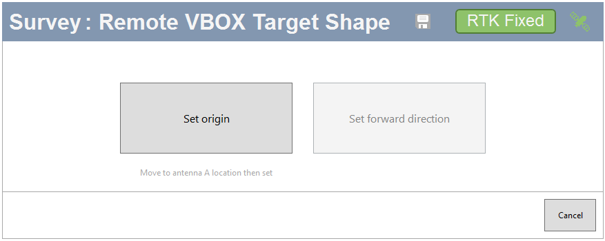
- Remove the survey antenna from the survey pole.
- Place the survey antenna on the vehicle roof where you want your origin point to be and click Set origin.
The origin should be at the same location as your primary antenna.
- Move the survey antenna forward and click Set forward direction.
The forward direction used in the configuration will be drawn from the origin point to your forward direction point. This should be along the centre of the vehicle and towards the front of the vehicle.
- Mount the survey antenna on the survey pole again.
- Place the survey pole next to the vehicle at a location that you wish to use as a vehicle point.
- Click on the Add vehicle point button to record the vehicle point.
- Repeat the process until you have set the required points (max 24).
Add 1 Line reference point:
- Use the survey pole and survey antenna to set the location of the point.
- Click the Add line ref. point button to record it.
- Click OK when you have added all your vehicle and line reference points.
- Click Write to unit to send the configuration to the connected VBOX unit.
Your target vehicle shape has now been configured.
Multiple Targets
If you want to use multiple targets, you need to repeat the target vehicle configuration above for each vehicle (Target Vehicle Hardware and Target Vehicle Shape)
- ►Edit points
-
Set points, without using surveying equipment, by manually entering offsets from the antenna.
You can set up to 24 vehicle points.
- Click on the Add vehicle point button to add a point to your vehicle shape.
- Add the X- and Y-axis distances (m) based on the antenna offset.
You can also set 1 Line reference point to your vehicle in this survey window.
- Click on the Add line ref. point button to add a line reference point to the Subject Vehicle.
- Measure from the primary GNSS antenna to the location you wish to use as the Line reference point.
- Add the X- and Y-axis distances (m) based on the antenna offset.
- Click OK when you have added all your vehicle and line reference points.
Your target vehicle shape has now been configured.
Multiple Targets
If you want to use multiple targets, you need to repeat the target vehicle configuration above for each vehicle (Target Vehicle Hardware and Target Vehicle Shape)
Surveying Reference Heading
|
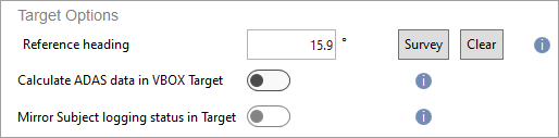 |
 |
|
| You can find more information about the ADAS Parameter Definitions here. |
Other ADAS Objects
You may need to use one or more other ADAS objects for reference in your test, such as static targets, road lines and sign posts. If you do need one or more of these, click on the blue heading for the object you want to add to see the steps.
- ►Static Targets
-
- Click Add Static Target.
Adding a Static Target at the current position:
- Click Add Static Target at current position.
- Reverse the vehicle > 20 m (or move the antenna backwards from the target).
- Click set target direction.
You can add up to 3 static targets.
Note: You can only have 5 targets in total, including both remote and static targets.
- Click Clear to delete added static targets.
- Click Save to save the added targets in a .VBC file.
- Click OK to finish.
- ► Lines
-
Lines are used to mark the edges of a road, lane or circuit during the testing. If the line you are surveying loops back on itself, for example, the centre line of a circular test track, you should add it as a Circuit Line.
You can have a maximum of 3 lines at any time.
Note: You will still be using the subject's VBOX unit to configure the lines.
Use the subject's VBOX unit.Open the ADAS menu in VBOX Setup.
Click Add Road Line to configure a new Road line or Add Circuit Line to add a new circuit line.
You now have two options, Load from File and Survey line.
-
Load From File
- Click on the Load from file button.
- Navigate to the file you wish to use.
- Click Load.
The file will be loaded into VBOX Setup and you can see the configured road lines.
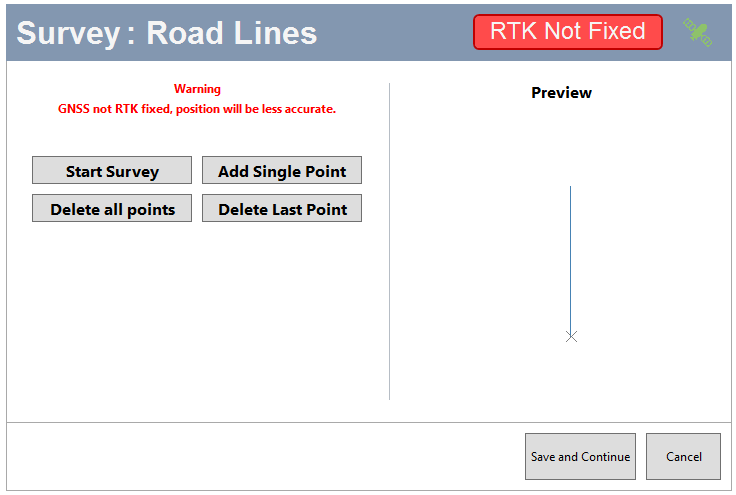
Survey Road Line
Click Survey Road Line.
There are 2 ways to survey a Road Line: To perform a survey and add single points.
Survey a Road Line
- Click Start Survey.
- Walk along the line you wish to use as a road line with the survey trolley.
- When you are happy with the surveyed line, click Save and continue.
- Click on the OK button to save the line and the Cancel button to exit the survey and go back to the ADAS menu.
Add Single Point
You can add single points to create a road line.
- Move the survey antenna to the first point of your line and click on the Add single point button.
- Move your survey antenna to the next point on your line and click on the Add single point button.
- Repeat this step until you have completed your Road Line.
- When you are happy with the surveyed line, click Save and continue.
- Click on the OK button to save the line and the Cancel button to exit the survey and go back to the ADAS menu.
Note:
- If you need to make changes to the added points, you can delete the last added point or clear all added points and start again.
Survey Circuit Line
Click Survey Circuit Line.
There are 2 ways to survey a Circuit Line: performing a survey or adding single points.
Survey a Road Line
- Click on the Start Survey button.
- Walk along the line you wish to use as a circuit line with the survey trolley.
- When you are happy with the surveyed line, click Complete Survey.
- Click on the OK button to save the line and the Cancel button to exit the survey and go back to the ADAS menu.
Add Single Point
You can add single points to create a circuit line.
- Move the survey antenna to the first point of your line and click on the Add single point button.
- Move your survey antenna to the next point on your line and click on the Add single point button again.
- Repeat this step until you have completed your circuit line.
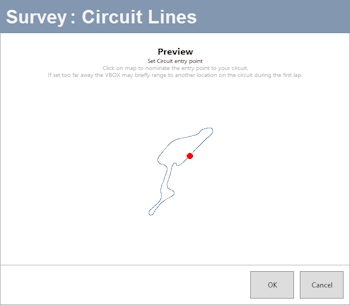
- When you are happy with the surveyed line, click Complete Survey.
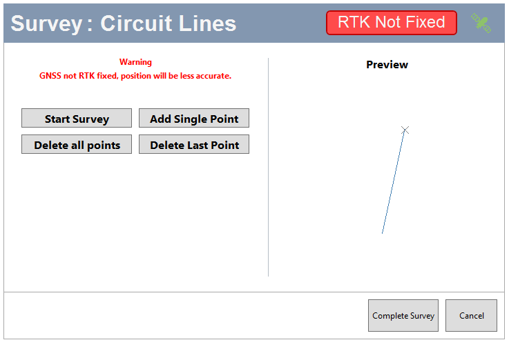
- Before you save the line, you can relocate the Entry Point (the red dot marks the entry point) on the track by clicking on the new location on the surveyed line.
If you do not move the entry point, Setup will place it at the location of the first point of the line.
- Click OK to save the line and Cancel to go back to the ADAS menu without saving the line.
Note:
- If you need to make changes in the added points, you can delete the last added point or clear all added points and start again.
- ►Sign Posts
-
By expanding the sign post section, you can enter data, such as:
- Sensor detection range
- Sensor detection angle
- Antenna to sensor offset
You can add up to 99 sign posts.
Note: You will still be using the subject's VBOX unit and its connected modules and laptop for this step.
- Click Add Sign Posts.
Add Sign Post at current position
- Move the survey antenna to the location of your sign post.
- Click on the Add Sign post at current position button.
- Repeat the process for each required sign post.
- When you have added the sign posts you need, click OK to continue.
To close the window without adding sign posts, click Cancel.
If you want to delete the added sign posts and start again, click Clear.
Step 4: Install and Connect all Subject Vehicle Hardware
| When you have finished configuring the ADAS objects, you can connect all the hardware on the Subject vehicle. |
|
.png?revision=1) |
Step 5: Send Configuration to Target(s)
|
If you have configured one or more target vehicles, and you wish to view the ADAS data on a connected display in your target vehicle(s), you will need to transfer the target vehicle configurations to the relevant target VBOX units.
Note: This process can take a couple of minutes. |
 |
Step 6: Final Checks
|
You should perform the following steps on all the vehicles in your test system before you start your test. Link TimeCheck the Link Time. Link Time is a good indicator of ADAS radio link quality. The VBOX ADAS system will suffer occasional single-sample drops outs. These are acceptable, but if this incremental count drops out and falls to zero, or has larger periods of time with full or intermittent drop-outs, it indicates a radio problem that needs addressing. This could, for example, be caused by issues with the radio system configuration or with the line of sight.
RTKYou should perform a final check to make sure that your RTK is fixed. If your RTK is not fixed, you could have a problem with the DGPS signal, radio setup, VBOX configuration, or environmental issues.
If you are using IMU…When used in conjunction with VBOX 3i RTK, data from the IMU is integrated with GPS data to improve the quality of measurements in areas with poor GPS reception.
When using IMU integration, it requires an initialisation phase when the IMU is first connected to the VBOX after being configured. This will automatically run after the VBOX unit has successfully gained GPS and RTK.
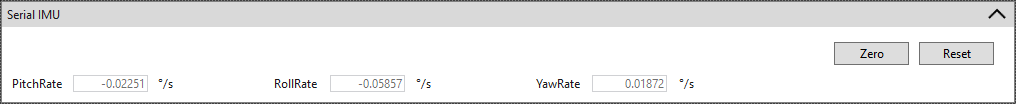
Gyro Rate OffsetsZero Gyro Rates These rate offsets are used to correct any gyro bias, making the Pitch, Roll and Yaw channels read zero when the vehicle is stationary. You can find these settings in the IMU menu in the VBOX Setup software, under the section heading Serial IMU.
Zero Click the Zero button to calibrate the rate offsets. The software will guide you through a calibration process. Reset Click the Reset button to remove the calibrated offsets and reset the rates to the default values.
True HeadingTrue heading offset is used to correct antenna alignment inaccuracies so that the true heading aligns with the course-over-ground heading when the vehicle travels in a straight line (for example, zero slip). You can either type in the true heading alignment if you have it or you can run the calibration. You can find the True Heading alignment setting in the Dual Antenna menu in VBOX Setup.
Range CheckCheck the range on the display to make sure that the vehicle shapes look and act as expected |


Step 7: Start Testing
| Your ADAS configuration should now be complete and you can start your test. You will be able to see live previews of the configured ADAS ranges during your test. |