VBOX 25 Hz Speed Sensor (v2) - Quick Start Guide
Getting Started
Registration
Please register your VBOX 25 Hz GPS Speed Sensor (v2) unit so that Racelogic can continue to provide you with notifications about the latest software releases and firmware upgrades for your Racelogic product and offer technical support.
Register your device here.
What is in the box?
 |
 |
|
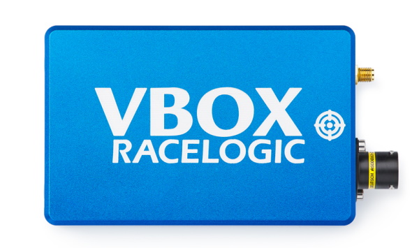
RLVBSS25-V2 VBOX 25 Hz GPS Speed Sensor (v2) |
|---|
| Product Code | Quantity | Description |
|---|---|---|
| VBSS25-V2 | 1 | VBOX 25 Hz GPS Speed Sensor unit |
| RLVBACS018 | 1 | Magnetic GNSS antenna (5 m cable) |
| RLCAB226 | 1 | Cable loom - Deutsch 23W ASDD - Multiple Connectors (1.2 m) |
| RLCALUKAS | 1 | Certificate of Calibration |
Note: You may have to order additional cables separately
Power Supply
VBOX 25 Hz Speed Sensor units is powered via the POWER IN banana plugs. Alternatively, you can use the CAN OUT + POWER lead on the loom to pass power to the Speed Sensor from a third-party device. Contact Racelogic Support for guidance
|
IMPORTANT
|
VBOX Speed Sensors have been designed to generate as little heat as possible and has a wide operating temperature range. It is, however, good practice to mount it in a position where it has sufficient airflow around the unit.
RLCAB226 Cable Loom
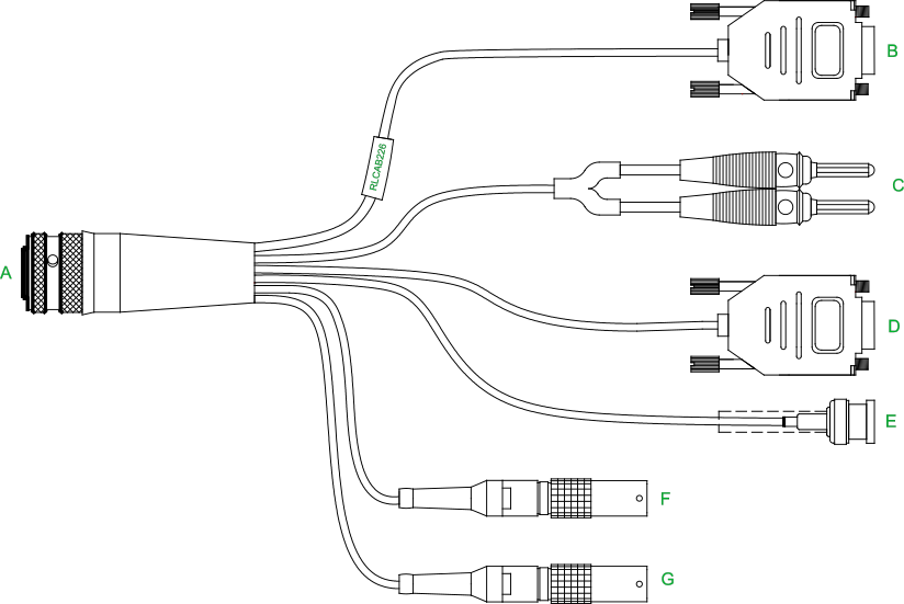
| Cable | Function | Cable | Function |
|---|---|---|---|
| A | UNIT CONNECTOR | E | DIGITAL OUT |
| B | SERIAL | F | DIGITAL IN |
| C | POWER IN | G | CAN OUT + POWER |
| D | CAN OUT |
Note: You can find the complete pinout information for the VBOX unit here.
Installation
Mounting
|
The VBOX 25 Hz Speed Sensor should be secured inside the vehicle to stop it from moving when the vehicle is in motion. The base plate has M3 screw holes along its length that you can use if you want to bolt it directly to a mounting surface in the vehicle. Alternatively, the Racelogic Mounting pole is compatible so you can mount the unit vertically. Contact vbox@racelogic.co.uk for more information or to order a mounting arm (RLACS212-V2) and/or mounting bracket (RLACS291). |
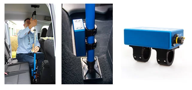 |
Antenna Placement
Appropriate placement of the GNSS antenna is crucial to the quality of the data that is being recorded.
Be aware of objects that can shadow the antenna or block the signal to the antenna. Some objects can also reflect signals which can send weaker GNSS signals to the antenna. This is called multipath, and these reflections can disturb the signal in an unpredictable way.
If an antenna is not mounted on a large enough ground plane, multipath reflections can also come from the ground beneath the antenna.
Note: You can find in-depth information about how to place the antenna on a vehicle and how to use the satellite elevation mask here.
Hardware Connections
.png?revision=1)
Note: You can find more information about the cable loom and the connector labels here.
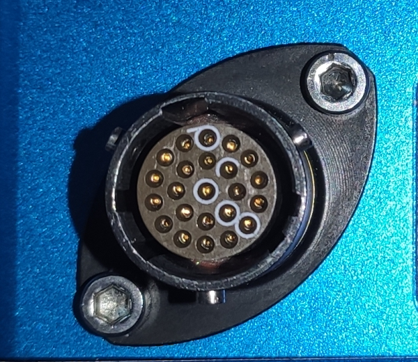
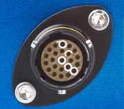
Connecting the Loom to the VBOX Unit
| Note: It is important that you do not use force when connecting and disconnecting the loom to the VBOX unit. |
 |
 |
|
|
|
 |
 |
 |
| Push the connectors gently together and twist the outer ring on the loom's connector until it slots in place and locks the connection. | ||
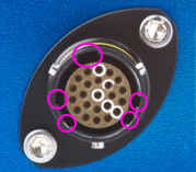
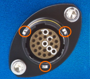
Disconnecting the Loom From the VBOX Unit
Note the notches on the connectors as illustrated above. Twist the loom's connector while you gently pull it away from the unit.
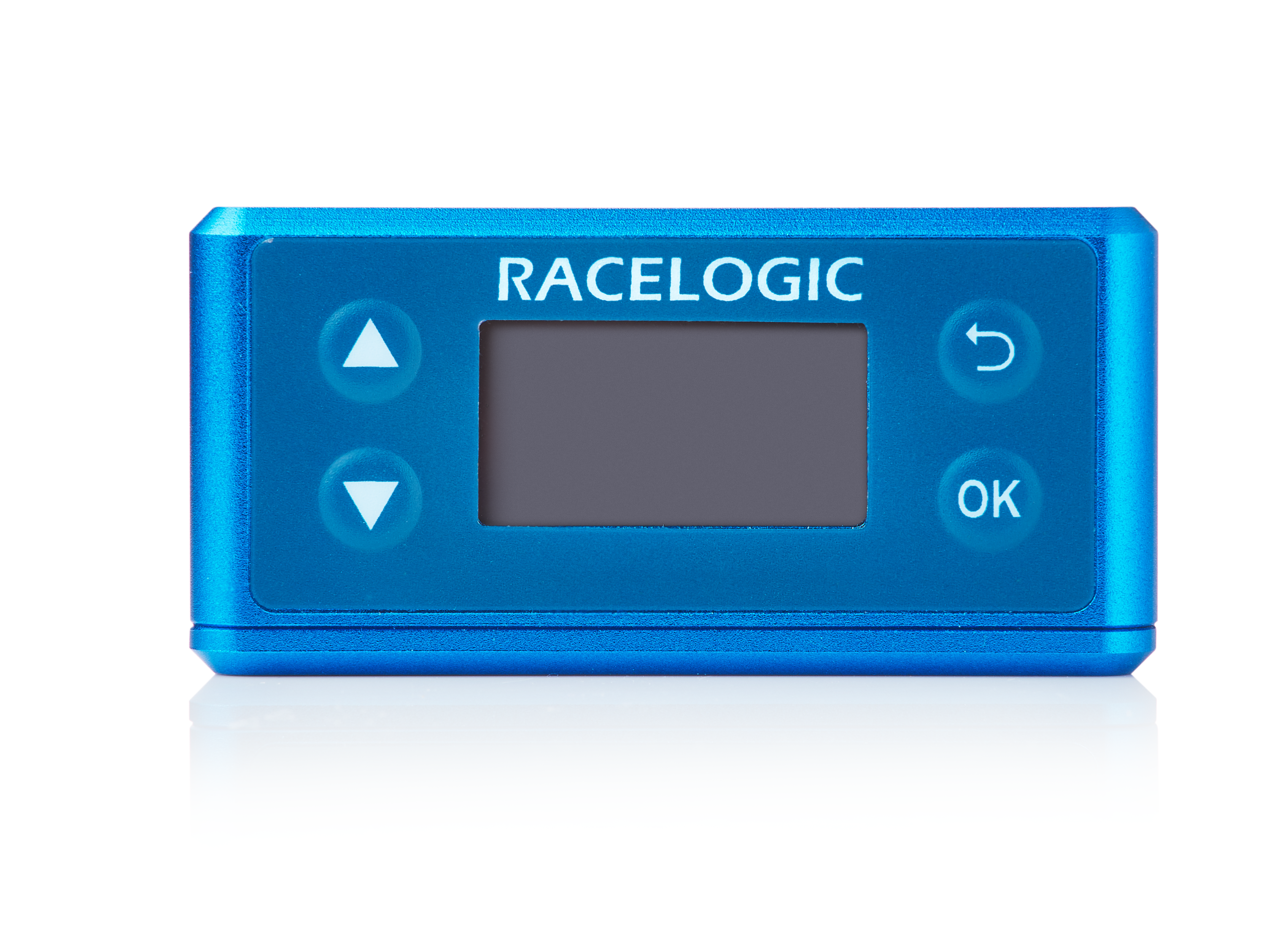
Front Panel
Overview
|
To facilitate unit configuration, the VBOX Speed Sensor has an OLED display and four membrane buttons on the front panel. Alternatively, you can use VBOX Setup to configure the VBOX unit. |
 |
Buttons
| Menu up / Increase the value when editing a number. |  |
Move to the previous menu level. | |
| Menu down / Decrease the value when editing a number. |
|
Enter the menu / select menu item for adjustment. |

Display
Startup
| When the VBOX Speed Sensor is powered up, it will display the RACELOGIC logo along with hardware variant and the serial number of the unit. Next, it will change to display the firmware version of the unit. | 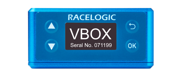 |
|
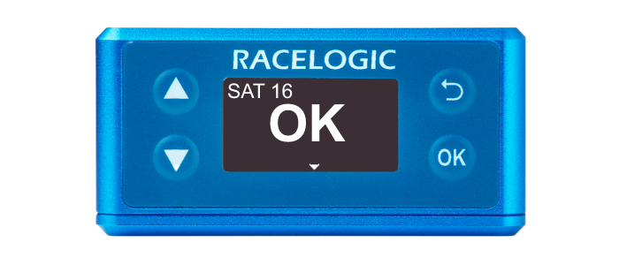
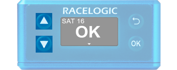
When the unit has initialised and any warnings have been cleared, the number of satellites will be displayed. |
 |
|
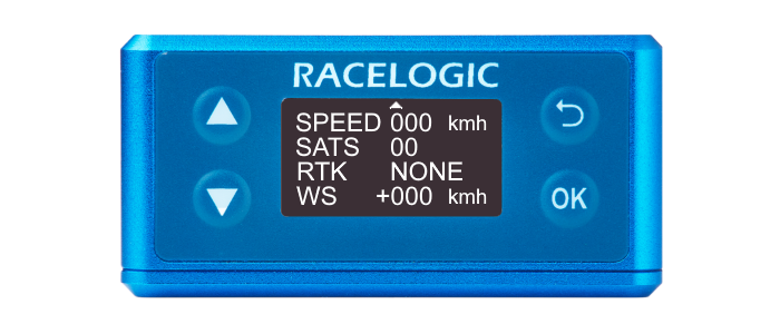
Press the Down arrow to open the status screen where you can view information about Speed, Satellite count, RTK Status and Wheel Speed. Press the Up arrow to return to the main screen. Note: RTK and wheel speed is not supported on the VBOX 25 Hz Speed Sensor (v2). |
 |
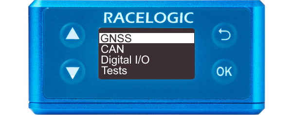
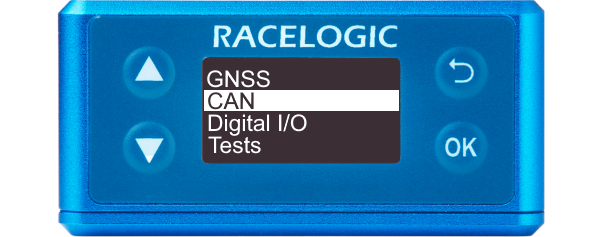
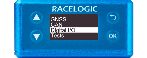
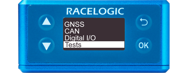
Settings Menu
| You can access the menu by pressing the OK button. Use the Up and Down arrows to navigate through the menu and press the OK button to enter a submenu. |
Factory Reset
| You can reset the unit to its factory settings by pressing the Up and Down arrow buttons simultaneously and holding them for 5 seconds. After this period, the unit will beep and it will play an audible confirmation signal when the reset is finished. |
 |
| Note: Receiver settings (Dynamic Mode, DGNSS Mode, DGNSS Rate and Elevation mask) will not reset. |
VBOX Setup
Introduction
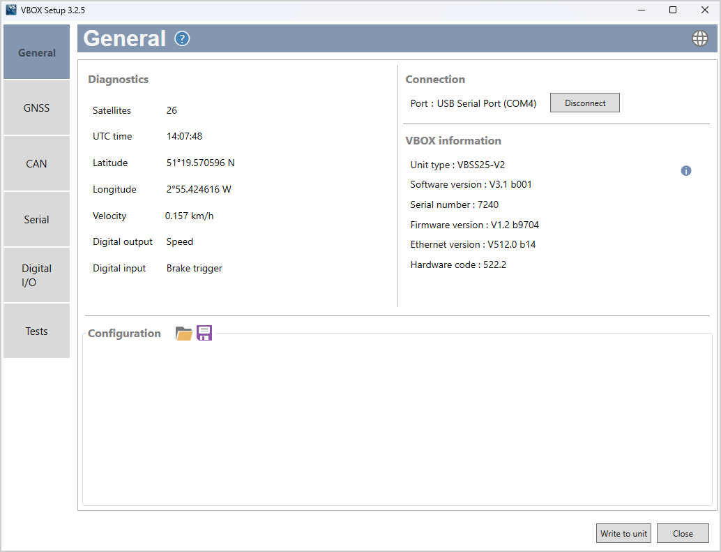
This is a general overview of the VBOX Setup software, connected to the VBOX 25 Hz Speed Sensor (v2), and its functionality. You can use the VBOX Setup Software to configure your VBOX unit. It provides greater functionality in comparison to using the Front Panel.
Connection
To configure a VBOX Speed Sensor unit, it needs to be connected to a power source and a computer.
You must use the VBOX Setup software to configure the unit. Use the supplied loom, connect the SERIAL lead and connector to the computer's serial port – you can also use a serial-to-USB converter if necessary.
IMPORTANT
Microsoft Windows 7 SP1 or newer is required (must be compatible with .Net Framework 4.7.1)
Once physically connected and powered, open the software and use the drop-down list to select the correct COM port that your VBOX unit is connected to. VBOX Setup automatically connects to the selected device and enters the setup screen for your unit.
.png?revision=1)
Note: An auto-detect message may appear if the baud rate has been changed from the default value - select ‘Yes’ to allow the different baud rates to be scanned.
Software Overview
| Available menus | The menu buttons in the sidebar allows you to navigate between the different settings menus. Click the buttons to select the desired menu. | 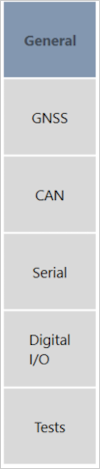 |
| Help | Clicking on the question mark icon when you have an active internet connection will open the corresponding user guide page for the menu within the Racelogic Support Centre. | |
| Current menu | The header displays the name of the menu that you have currently selected. |  |
| Language | By clicking the globe icon, you can select the language that VBOX Setup is displayed in. |  |
| Settings area | This is the main area of the screen that will show relevant settings and information. | 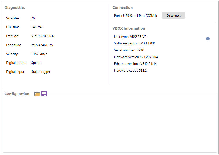 |
| Write to unit | After making changes to your setup, the Write to Unit button should be selected to ensure the settings have been uploaded to the connected VBOX unit. |  |
| Close | Clicking this button closes the software. You will be prompted to save the settings if the changes have not been written to the VBOX unit. |  |
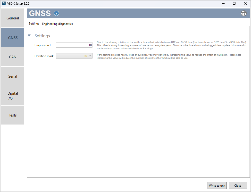
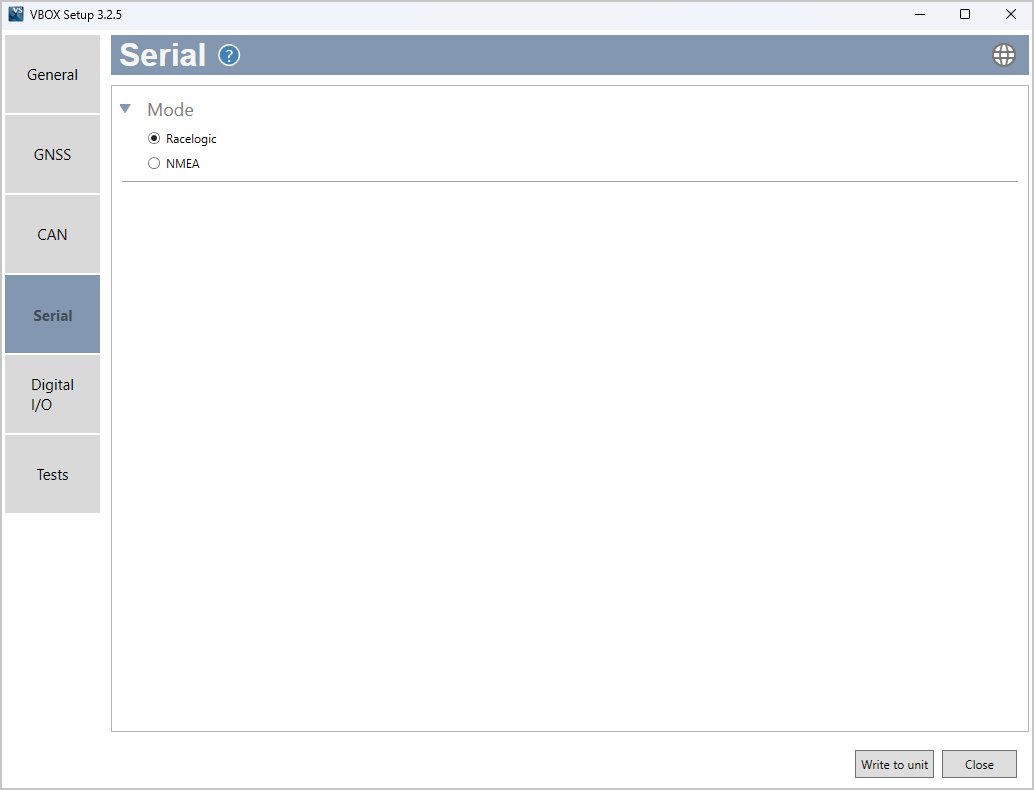
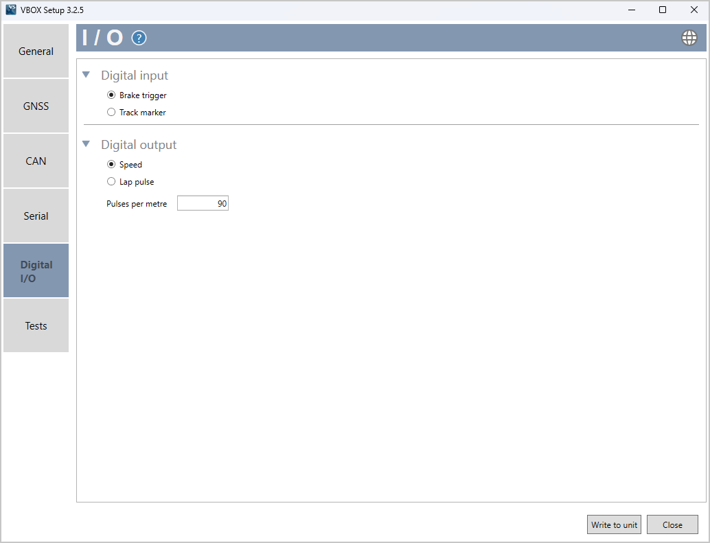
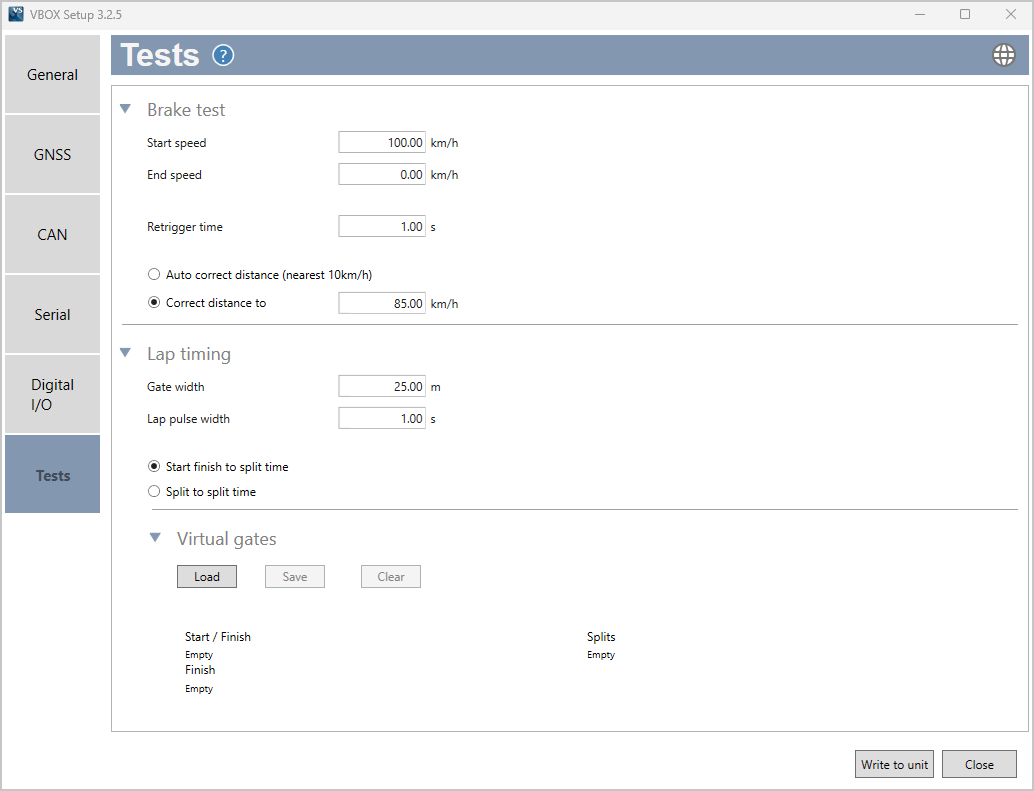
Settings Menus
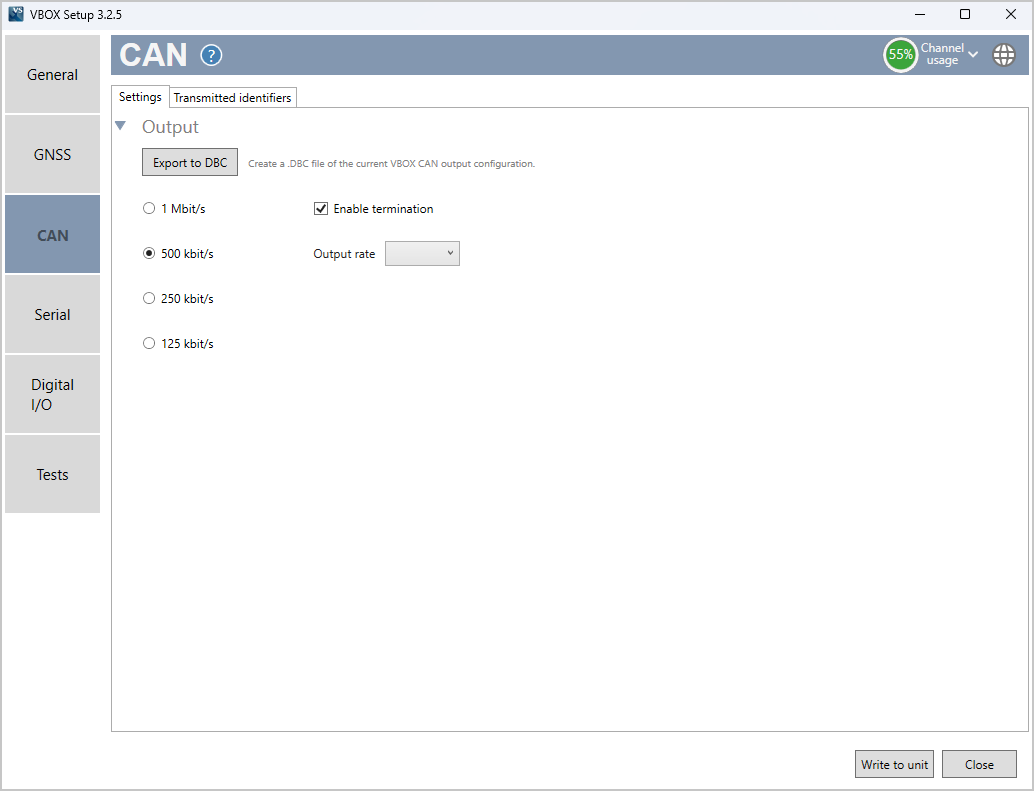
The sidebar enables you to switch between the different settings menus; General, GNSS, CAN, Serial, Digital I/O and Tests. Click on the menus below to view more information.
|
|
|
 |
|
|
|
|