Using VBOX 3i products with Wheel Speeds
Introduction
GPS measurement of speed, position and acceleration has become an essential part of the process in assessing the performance of many aspects of a vehicle. Test tracks are rarely perfect places for satellite reception, with trees, bridges and tunnels all having an effect on the quality of the measured data. When the tests are carried out on the road, this problem becomes even greater, with more objects obscuring the direct view to the satellites.
VBOX 3i can limit these obstacles by utilising the latest multi-frequency, multi-constellation GPS receiver and integrating inertial and vehicle speed data.
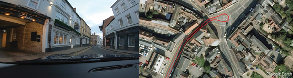
Accuracy within a built-up urban area
An added advantage of using multi-frequency techniques is the time taken to recover accuracy after a bridge or tunnel is often less than 2 seconds. In areas where there is no view of the sky at all, such as tunnels, inertial sensors and wheel-speeds can fill in the gaps for periods of up to 5 minutes.
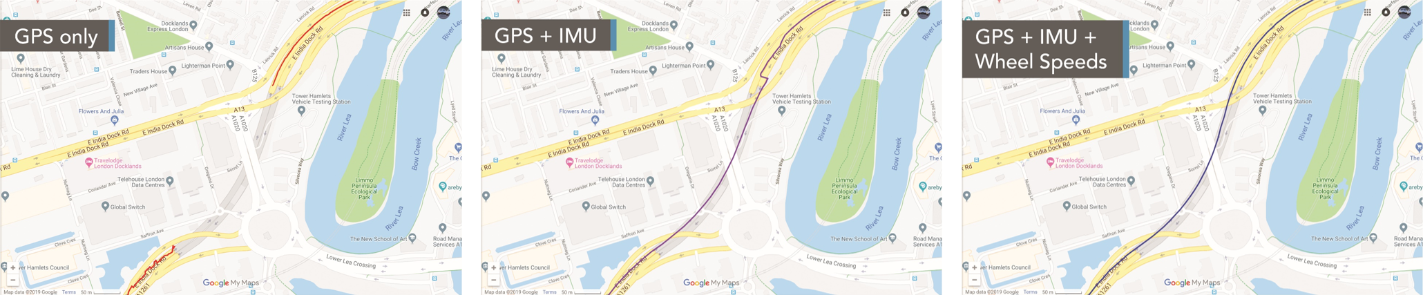 Accuracy through tunnel
In the data above, you can clearly see the difference that the inertial and wheel-speed data is making to the accuracy of the estimated trajectory, with the IMU doing a good job of estimating the position during the tunnel, ending up with a 15 m error at the end (purple trace). Adding the wheel-speeds into the system (blue trace) significantly reduces the errors, tracking the vehicle through the tunnel with great accuracy.
Configuration
To use wheel speeds, you must first configure VBOX 3i. The configuration steps depend on the hardware and firmware you are using.
VBOX Setup
- VBOX 3i ADAS
- VBOX 3i RTK V3-V5 (FW v3.0)
- VBOX 3i RTK V3-V5 (FW v2.8)
- VBOX 3i Dual Antenna V3-V5 (FW v3.0)
- VBOX 3i Dual Antenna V3-V5 (FW v2.8)
- VBOX 3i Single Antenna V3-V5 (FW v3.0)
- VBOX 3i Single Antenna V3-V5 (FW v2.8)
Note: If you are using an older hardware or firmware version, you can find the integration information in the relevant VBOX 3i User Guide.
VBOX Manager
If you need to use a VBOX Manager to integrate the IMU, you can use the IMU-INS menu to enable the IMU integration mode.
Wheel Speed Inputs
In order to obtain the wheel speed information, the best solution is to use the sensors already fitted to the vehicle by connecting to the vehicle’s CAN bus by using an RLCAB069L, RLCAB015L or RLACS182L cable. Before you start testing, you must make sure that the VBOX 3i unit is correctly connected to either the speed sensors or to the vehicle CAN bus.
Wheel speed input needs to be Enabled and configured, this can be done via the VBOX Setup Software.
VBOX Setup
The configuration steps depend on the hardware and firmware you are using.
- VBOX 3i ADAS
- VBOX 3i RTK V3-V5 (FW v3.0)
- VBOX 3i RTK V3-V5 (FW v2.8)
- VBOX 3i Dual Antenna V3-V5 (FW v3.0)
- VBOX 3i Dual Antenna V3-V5 (FW v2.8)
- VBOX 3i Single Antenna V3-V5 (FW v3.0)
- VBOX 3i Single Antenna V3-V5 (FW v2.8)
Note: If you are using an older hardware or firmware version, you can find the integration information in the relevant VBOX 3i User Guide.
Dynamic Mode
Note: This step does not apply to VBOX 3i ADAS units.
The dynamic mode should be set to High dynamics. You can do this in the VBOX Setup Software or with the VBOX Manager. You can find more information on Dynamic Modes here.
VBOX Setup Software
The configuration steps depend on the hardware and firmware you are using.
- VBOX 3i RTK V3-V5 (FW v3.0)
- VBOX 3i RTK V3-V5 (FW v2.8)
- VBOX 3i Dual Antenna V3-V5 (FW v3.0)
- VBOX 3i Dual Antenna V3-V5 (FW v2.8)
- VBOX 3i Single Antenna V3-V5 (FW v3.0)
- VBOX 3i Single Antenna V3-V5 (FW v2.8)
Note: If you are using an older hardware or firmware version, you can find the integration information in the relevant VBOX 3i User Guide.
VBOX Manager
If you need to use a VBOX Manager to configure the dynamic mode, you can use the Dynamic mode setting in the VBOX menu.
Elevation mask
You may also have to adjust the Satellite Elevation Mask depending on the environment. You can find more information about this here.
VBOX Setup
The configuration steps depend on the hardware and firmware you are using.
- VBOX 3i RTK V3-V5 (FW v3.0)
- VBOX 3i RTK V3-V5 (FW v2.8)
- VBOX 3i Dual Antenna V3-V5 (FW v3.0)
- VBOX 3i Dual Antenna V3-V5 (FW v2.8)
- VBOX 3i Single Antenna V3-V5 (FW v3.0)
- VBOX 3i Single Antenna V3-V5 (FW v2.8)
Note: If you are using an older hardware or firmware version, you can find the integration information in the relevant VBOX 3i User Guide.
VBOX Manager
If you need to use a VBOX Manager to configure the elevation mask, you can use the Elevation mask setting in the VBOX menu.