Connector 1 - I/O (Deutsch Autosport 23 PIN)
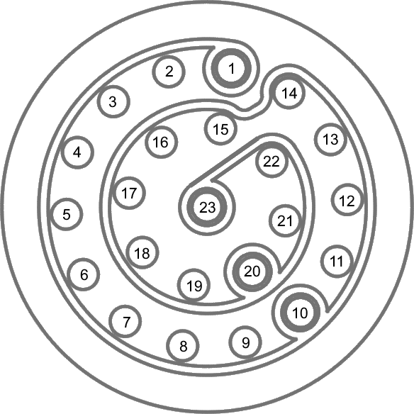
| PIN | I/O | Function |
|---|---|---|
| 1 | - | Aux RS232 Tx |
| 2 | - | Aux RS232 Rx |
| 3 | I/O | Ethernet Tx+ |
| 4 | I/O | Ethernet Tx- |
| 5 | I/O | Ethernet Rx- |
| 6 | I/O | Ethernet Rx+ |
| 7 | I | CAN in - low |
| 8 | I | CAN in - high |
| 9 | O | CAN out - high |
| 10 | O | CAN out - low |
| 11 | I | Digital in |
| 12 | O | Power return |
| 13 | I | Power in |
| 14 | O | Digital out |
| 15 | - | Ground (unit configuration interface) |
| 16 | I | RS232 Rx data (DGPS corrections interface) |
| 17 | I | RS232 Tx data (DGPS corrections interface) |
| 18 | I | RS232 Rx data (Serial -- ADAS config) |
| 19 | I | RS232 Tx data (Serial -- ADAS config) |
| 20 | - | Ground |
| 21 | O | Power out (CAN and Power out) |
| 22 | O | Power out (Aux) |
| 23 | I/O | 1PPS (Aux) |
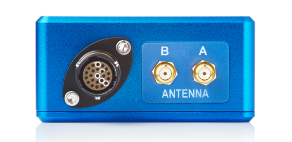
Connector 2 - Antenna

| PIN | I/O | Function |
|---|---|---|
| Centre | - | RF Signal / Power for active antenna |
| Chassis | - | Ground |
Connector 3 - Antenna
| PIN | I/O | Function |
|---|---|---|
| Centre | - | RF Signal / Power for active antenna |
| Chassis | - | Ground |
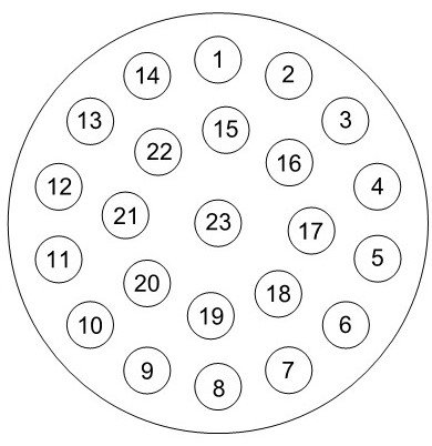
| PIN | I/O | Function |
|---|---|---|
| 1 | O | Digital Output |
| 2 | - | Ground (digital output/DGPS) |
| 3 | O | RS232 Tx data (DPGS corrections interface) |
| 4 | PWR | DGPS power out |
| 5 | PWR | Speed sensor power ground |
| 6 | PWR | Speed sensor power 6.5 - 30 V DC |
| 7 | PWR | CAN 2 power out |
| 8 | PWR | CAN 2 power ground |
| 9 | I/O | CAN 2 low |
| 10 | I/O | CAN 2 high |
| 11 | I/O | CAN 1 low |
| 12 | I/O | CAN 1 high |
| 13 | I | Digital input |
| 14 | - | Ground (digital input) |
| 15 | - | Ground (unit configuration interface) |
| 16 | I | RS232 Rx data (DGPS corrections interface) |
| 17 | PWR | External IMU power ground |
| 18 | PWR | External IMU power out |
| 19 | I | RS232 Rx data (external IMU interface) |
| 20 | O | RS232 Tx data (external IMU interface) |
| 21 | I | RS232 Rx data (unit configuration interface) |
| 22 | O | RS232 Tx data (unit configuration interface) |
| 23 | O | 1 PPS output (external IMU interface) |
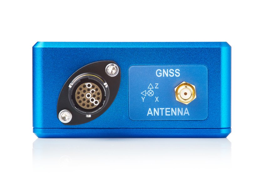
Connector 2 - Antenna
| PIN | I/O | Function |
|---|---|---|
| Centre | - | RF signal / Power for active antenna |
| Chassis | - | Ground |
Connector 3 - Antenna
| PIN | I/O | Function |
|---|---|---|
| Centre | - | RF signal / Power for active antenna |
| Chassis | - | Ground |
Connector 1 - I/O (Deutsch Autosport 23 PIN)
| PIN | I/O | Function |
|---|---|---|
| 1 | - | Aux RS232 Tx |
| 2 | - | Aux RS232 Rx |
| 3 | I/O | Ethernet Tx+ |
| 4 | I/O | Ethernet Tx- |
| 5 | I/O | Ethernet Rx- |
| 6 | I/O | Ethernet Rx+ |
| 7 | I | CAN in - low |
| 8 | I | CAN in - high |
| 9 | O | CAN out - high |
| 10 | O | CAN out - low |
| 11 | I | Digital in |
| 12 | O | Power return |
| 13 | I | Power in |
| 14 | O | Digital out |
| 15 | - | Ground (unit configuration interface) |
| 16 | I | RS232 Rx data (DGPS corrections interface) |
| 17 | I | RS232 Tx data (DGPS corrections interface) |
| 18 | I | RS232 Rx data (Serial config) |
| 19 | I | RS232 Tx data (Serial config) |
| 20 | - | Ground |
| 21 | O | Power out (CAN and Power out) |
| 22 | O | Power out (Aux) |
| 23 | I/O | 1PPS (Aux) |
Connector 2 - Antenna
| PIN | I/O | Function |
|---|---|---|
| Centre | - | RF Signal / Power for active antenna |
| Chassis | - | Ground |
Connector 3 - Antenna
| PIN | I/O | Function |
|---|---|---|
| Centre | - | RF Signal / Power for active antenna |
| Chassis | - | Ground |