| PIN | I/O | Function | |||
|---|---|---|---|---|---|
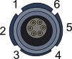
| 1 | I | Charge + | |||
| 2 | I | Charge – | |||
| 3 | I/O | CAN High | |||
| 4 | I/O | CAN Low | |||
| 5 | I | Switch + | |||
| 6 | I | Switch – |

| PIN | I/O | Function | |||
|---|---|---|---|---|---|
| 1 | I | Charge + | |||
| 2 | I | Charge – | |||
| 3 | I/O | CAN High | |||
| 4 | I/O | CAN Low | |||
| 5 | I | Switch + | |||
| 6 | I | Switch – |

| PIN | I/O | Function | |||
|---|---|---|---|---|---|
| Center | N/A | RF Signal/Power for active antenna | |||
| Chassis | N/A | Ground |

| PIN | I/O | Function | |||
|---|---|---|---|---|---|
| Center | N/A | RF Signal/Power for active antenna | |||
| Chassis | N/A | Ground |

| PIN | I/O | Function | |||
|---|---|---|---|---|---|
| 1 | O | NC | |||
| 2 | I | NC | |||
| 3 | I/O | CAN High | |||
| 4 | I/O | CAN Low | |||
| 5 | O | + V Power (Same as Power +) |

| PIN | I/O | Function | |||
|---|---|---|---|---|---|
| 1 | O | NC | |||
| 2 | I | NC | |||
| 3 | I/O | CAN High | |||
| 4 | I/O | CAN Low | |||
| 5 | O | + V Power (Same as Power +) |